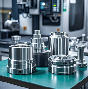
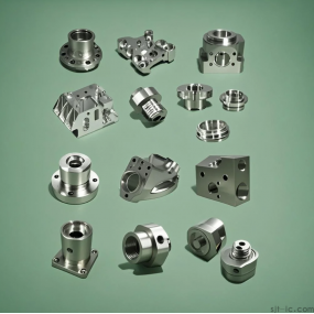
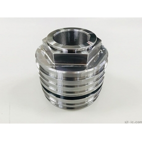
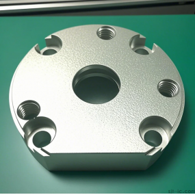
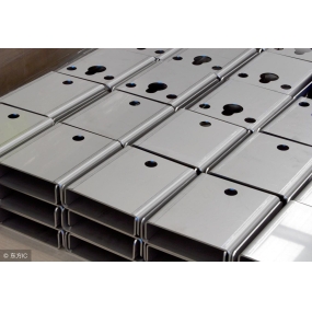
The structure of the thin plate aluminum parts is simple, but because the material of the parts is aluminum alloy, and the cavity bottom and cavity wall are relatively thin, the biggest problem in processing is how to prevent the deformation of the workpiece cavity baseplate and cavity wall. In particular, the deformation of the cavity baseplate is the largest, the middle arching is uneven, and the thickness of the baseplate is uneven. The middle of the baseplate is milled too much due to the arching, and the middle thickness of the processing result of the baseplate is the thinnest, which is greatly different from the periphery. Based on this, in processing practice, it is necessary to combine the characteristics of the thin plate aluminum parts and scientifically formulate the processing technology to ensure that the processing quality of the aluminum parts meets the standard requirements.
Technological analysis of numerical control machined parts
The dimensioning method on the part drawing should adapt to the characteristics of numerical control machining. On the numerical control machining part drawing, the size should be given with the same reference or the coordinate size should be given directly. This labeling method is convenient for programming and coordination between dimensions. Since the numerical control machining accuracy and repeated positioning accuracy are very high, it will not destroy the use characteristics due to large accumulation errors. Therefore, the local scattered labeling method can be changed to the same reference annotation size, or the coordinate size can be given directly. In addition, the conditions of the geometric elements that make up the contour of the part should be sufficient to avoid being unable to start during programming.
It is best to use a uniform geometric type and size for the inner cavity and shape of the part, which can reduce the size of the tool and the number of tool changes, make the programming convenient and improve the production efficiency. The size of the fillet of the inner groove determines the size of the tool diameter, so the fillet radius of the inner groove should not be too small. The quality of the workmanship of the part is related to the height of the contour to be machined, the size of the arc radius of the transfer, etc. When milling the bottom plane of the part, the fillet radius r of the bottom of the groove should not be too large, and a unified reference positioning should be adopted. In numerical control machining, in order to ensure the accuracy of its relative position after two clamping machining, a unified reference positioning should In addition, it is also necessary to analyze whether the required machining accuracy, dimensional tolerances, etc. of the parts can be guaranteed, whether there are any extra dimensions that cause contradictions or closed dimensions that affect the process arrangement.
Second, determine the processing method and processing plan
The selection principle of the processing method is to ensure the processing accuracy and surface roughness requirements of the machined surface. Since there are generally many processing methods to obtain the same level of accuracy and surface roughness, the actual selection should be based on the shape, size and heat treatment requirements of the parts. For example, thin-walled aluminum parts are easily deformed, so ordinary processing and
The method of combining numerical control machining is used to optimize the combined machining process, reduce the manufacturing cycle of the parts, and improve the machining efficiency of the parts. The parts are basically processed by the processing method of rough and finishing grooves by punching holes and tapping (including making two process pin holes) in the shape of the rough and finishing car. The processing of relatively precise surfaces on the parts is often achieved gradually through roughing, semi-finishing and finishing. It is not enough to choose the corresponding final processing method for these surfaces only according to the quality requirements. It is also necessary to correctly determine the processing plan from the blank to the final shape. When determining the processing plan, the processing method required to meet these requirements should be initially determined according to the requirements of the accuracy and surface roughness of the main surface. For example, after roughing or semi-finishing a space arc surface with high accuracy requirements, a ball end milling cutter must also be used for 45 or 135 small spacing (generally between 0.1 and 0.2 meters with high accuracy requirements).
Analysis of numerical control milling process for thin aluminum parts
(I) Heat treatment
The blank material of the parts in Figure 1 is LY12, which is a typical hard aluminum alloy in the aluminum-copper-magnesium series. Its composition is more reasonable and the comprehensive properties are better. The alloy is characterized by: high strength, certain heat resistance, and can be used as working parts below 150 C. The forming performance is better in the hot state, annealing and new quenching state. The heat treatment strengthening effect is remarkable, but the heat treatment process requires strict. If conditions are best, heat treatment is carried out to improve the hardness after aging.
(2) Blanking
The rough material is a large aluminum plate rolled, which needs to be cut into a 144 mm 114 mm 12 mm small plate. Since the rolled aluminum plate has a grain direction (the double-dot line in Figure 2 indicates the rolling grain direction), pay attention to the cutting as shown in Figure 2, so that the length direction of the small plate is perpendicular to the grain direction of the large plate.
(3) numerical control milling
During the machining process, UG6.0 software is used for modeling and programming.
First, the bottom surface is clamped, and the front roughing process is shown in Table 1, which is a summary of the front roughing process.
Second, flipping, rough milling chuck This thin-walled part is processed, the biggest problem is that it is prone to deformation during processing. In order to prevent deformation, the bottom chuck cannot be milled in place at one time, and the clamping problem during front finishing is taken into account, because the thickness of the bottom flange is only 2 mm. If it is milled in place, it is difficult to clamp with flat pliers. Therefore, in order to facilitate the clamping during front finishing and not cause large deformation when going to the bottom chuck after front finishing, when modeling this part in UG, 4 bosses are specially added to the bottom surface. The boss size is 15 mm 10 mm 3.7 mm, and the bottom surface finishing margin of 0.3 mm is specially set aside during modeling. In this way, the existence of four bosses, on the one hand, facilitates the clamping during front finishing, and on the other hand, it can ensure that after removing the large margin of the bottom surface, the small margin (boss chuck and 0.3 mm thick margin) will not be removed during the next bottom surface finishing, so as not to cause large deformation of the workpiece due to the large cutting force.
Third, fine milling. When finishing milling the front, pay special attention to the appropriate clamping force during clamping. If it is too large, it will arch the middle of the part and make the central part of the bottom surface of the inner cavity thin. In order to prevent cutting deformation, the method of first semi-fine milling and then fine milling is adopted. Then rough and fine milling have 2 notches. When the notch is rough milling, the amount of cutters should be small, and the layer is given priority; and when finishing milling, depth is given priority. Rough milling and fine milling both use up-milling, which can effectively prevent the deformation of the notch.
Fourth, completely remove the bottom surface. The chuck is first rough milled with a quasi-16mm end mill for 4 bosses. Since the bottom surface is a large plane, a face milling cutter is generally used for milling, but after experiments, it is found that the use of a face milling cutter will cause a large deformation of the bottom surface of the part. Therefore, the use of a small diameter milling cutter, although the efficiency is reduced, can ensure that the workpiece is not easily deformed. The spindle rotates forward, the chips fly outside the part, and the cutting force presses the workpiece down, making the workpiece close to the pad iron and not easy to deform. Note that the tool route cannot go in the opposite direction relative to Figure 4, because the cutting force picks the workpiece up, and the thin plate workpiece is easily deformed when it leaves the pad iron After rough milling of the boss, the bottom surface is still left with a margin of 0.3 mm thick and 144 mm long and 114 mm wide, but this part of the material cannot be removed with a face milling cutter, otherwise the deformation will be large. After testing, a quasi-16 mm end mill was used to fine milling the bottom surface, and the bottom surface was deformed greatly, and the parts were unqualified. Finally, a flying knife was used, 2 self-grinding knives were used, and the knives were like external turning tools used on lathes to fly flat the large plane of the bottom surface. Since the length, width and size of this part are not much different, you can first install the clamping width 106 mm and fly it on both sides, and then replace it with a 136 mm long side and fly it again. In this way, the deformation of the bottom surface is minimal, and qualified parts can be
IV. Conclusion
In summary, the processing technology described in this paper can effectively ensure the processing quality of such thin-walled and thin-sheet aluminum parts, effectively reduce the deformation rate, shorten the product manufacturing cycle, and improve the quality, accuracy and production efficiency of the product.


 English
 Spanish
 Arabic
 French
 Portuguese
 Belarusian
 Japanese
 Russian
 Malay
Malay Icelandic
 Bulgarian
 Azerbaijani
 Estonian
 Irish
Irish Polish
 Persian
 Boolean
 Danish
 German
 Filipino
 Finnish
 Dutch
Dutch Galician
 Catalan
 Czech
Czech Croatian
 Latin
Latin Latvian
 Romanian
 Maltese
 Macedonian
 Norwegian
 Swedish
 Serbian
 Slovak
 Slovenian
 Swahili
 Thai
Thai Turkish
 Welsh
Welsh Urdu
Urdu Ukrainian
 Greek
Greek Hungarian
 Italian
 Yiddish
 Indonesian
 Vietnamese
 Haitian Creole
 Spanish Basque

