English
 Spanish
 Arabic
 French
 Portuguese
 Belarusian
 Japanese
 Russian
 Malay
Malay Icelandic
 Bulgarian
 Azerbaijani
 Estonian
 Irish
Irish Polish
 Persian
 Boolean
 Danish
 German
 Filipino
 Finnish
 Korean
 Dutch
Dutch Galician
 Catalan
 Czech
Czech Croatian
 Latvian
 Romanian
 Maltese
 Macedonian
 Norwegian
 Swedish
 Serbian
 Slovak
 Slovenian
 Swahili
 Thai
Thai Turkish
 Welsh
Welsh Urdu
Urdu Ukrainian
 Greek
Greek Hungarian
 Italian
 Yiddish
 Indonesian
 Vietnamese
 Haitian Creole
 Spanish Basque

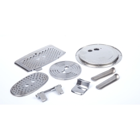
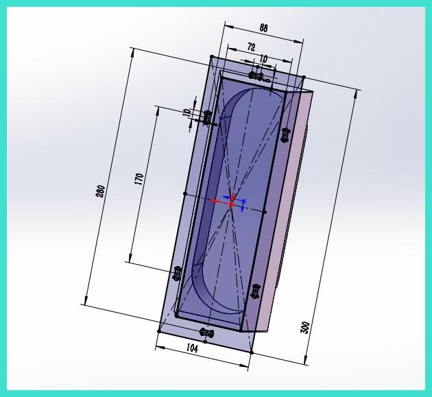
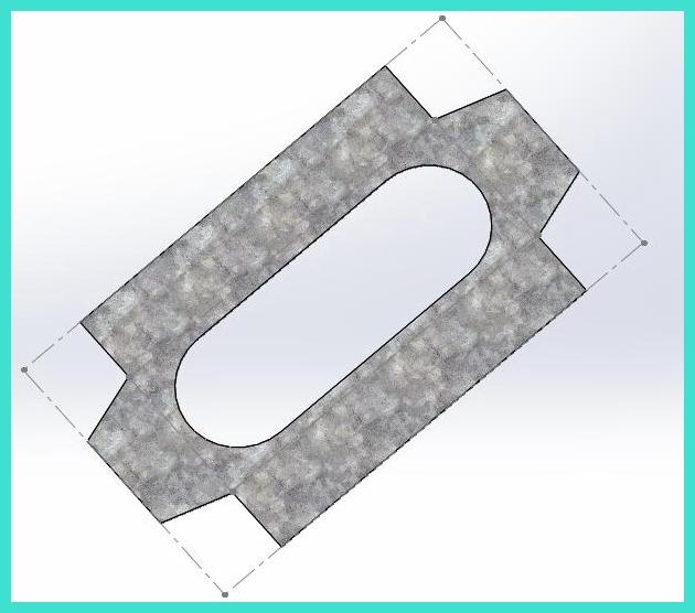
Haec pictura ostendit partem metallam lapidem aeris. Haec articulus sublime explicat quomodo hoc lapidem metallam partem facere et dissolvi? Hoc articulum focus est in drawinge medio anguli flange!
Imagine 3D: 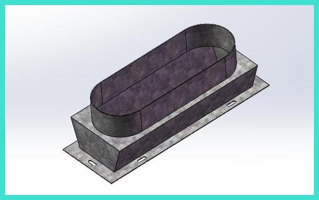
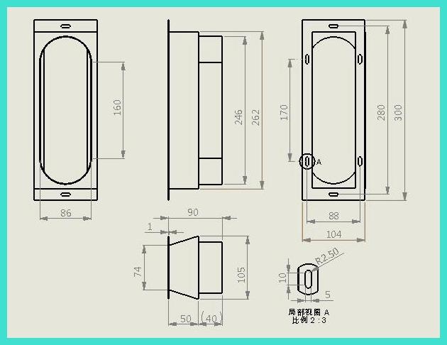
Design engineering 2D:
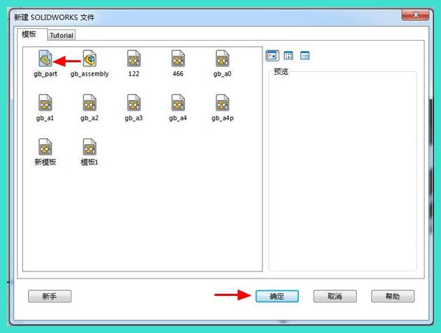
Stepes drawingis sunt sicut: 1. Aperi software SolidWorks, † New † - † Parts †
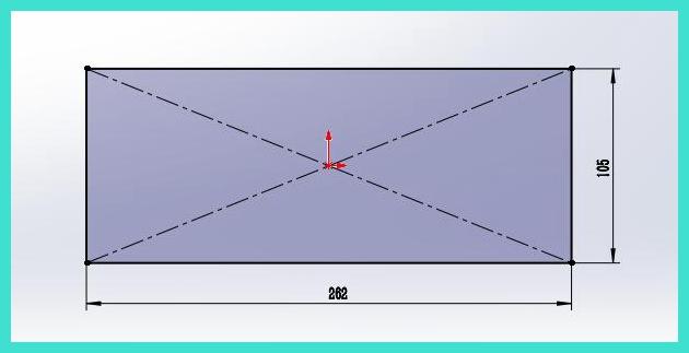
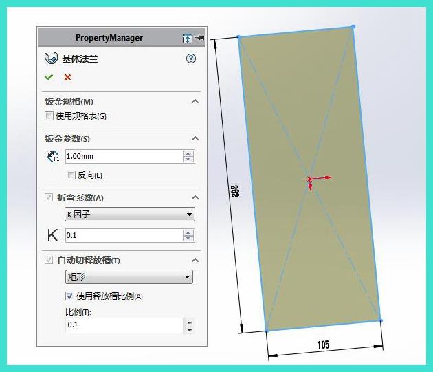
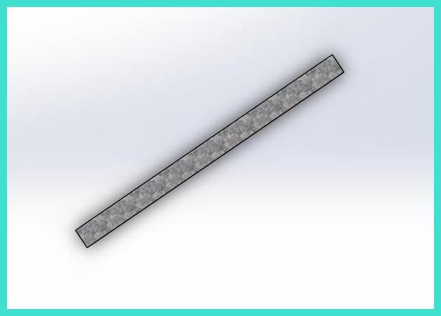
2. First, draw the base flange of the middle part 762 * 105. Click on [Sketch] to draw the sketch first
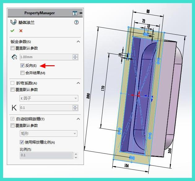
3. Click on "Base Flange" to set the plate thickness to 1mm, and set the bending coefficient a K factor of 0.1. 90 degree bending, large arc bending, set bending coefficient separately
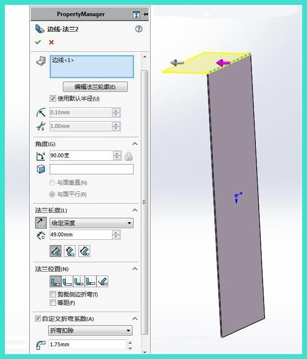
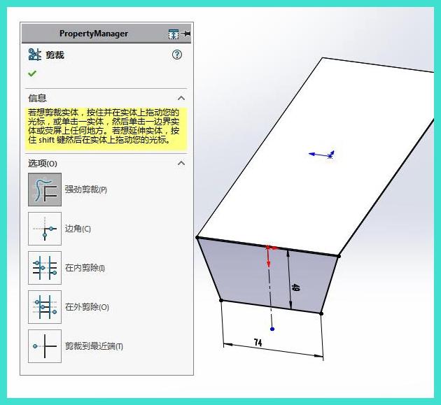
4. Click on [Edge Flanges] to set the angle to 90 degrees and depth to 49 degrees, and deduct 1.75 for bending
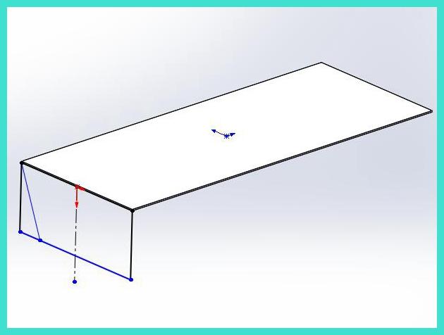
5. Edit the sketch of the edge flange
6. Click on [Mirror]
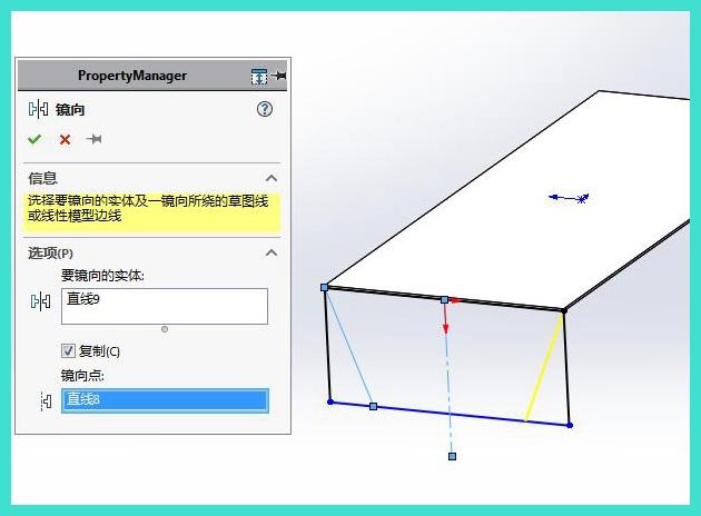
7. Click on the dimension annotation to generate the edge flange
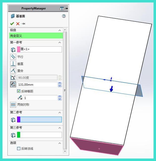
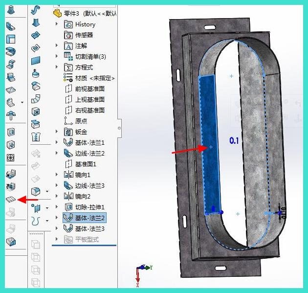
8. Click on [Reference Surface] to create a new reference surface with an offset distance of 131mm
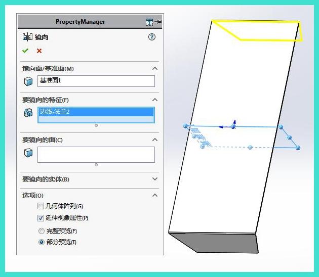
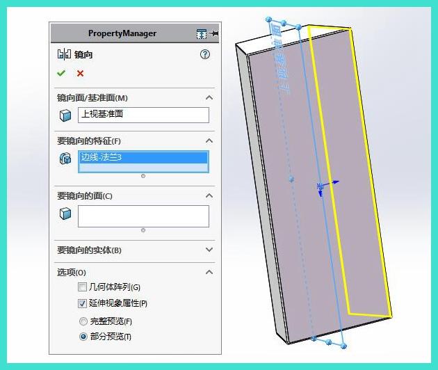
9. Click on "Mirror" to select the newly created reference plane 1 for the mirror reference plane, and select the edge flange for the feature to be mirrored
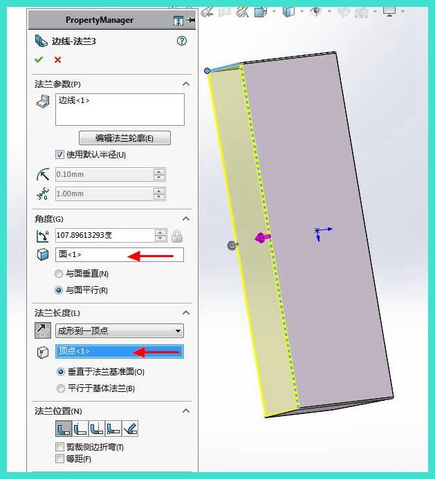
10. Click on the "Edge Flanges" button. The arrow in the figure below is the key setting point
11. Click on the [Mirror] reference plane to select the upper reference plane, and select the edge flange of the previous step for the feature to be mirrored
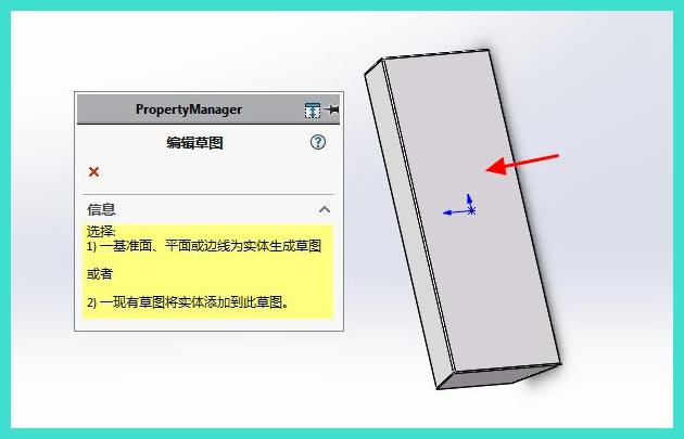
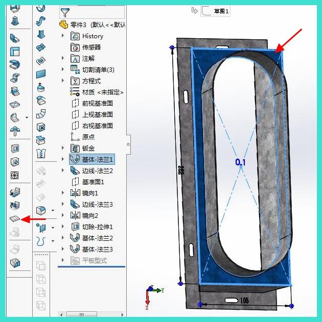
12. Click on [Sketch] to draw the sketch reference plane and select the plane indicated by the arrow
13. Draw a stretching and cutting sketch
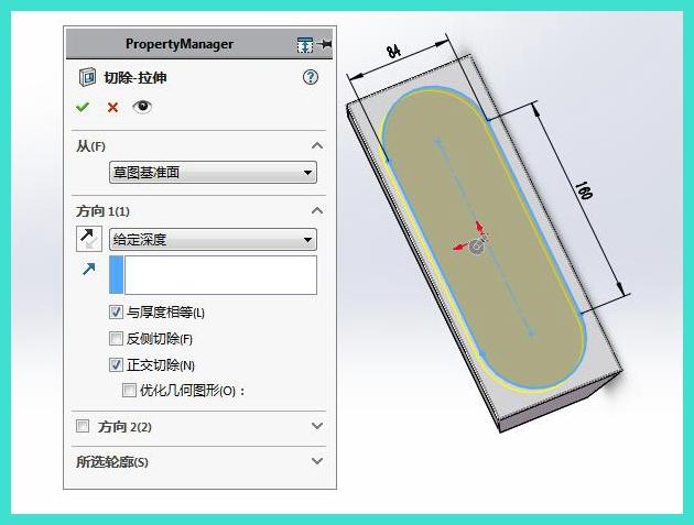
14. Click on stretching cutting and set parameters
15. Click on [Sketch] to draw the sketch reference plane and select the plane indicated by the arrow
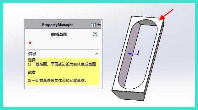
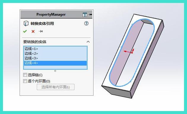
16. Draw a sketch and click on 'Entity Conversion Reference' to select the edge line for stretching and cutting
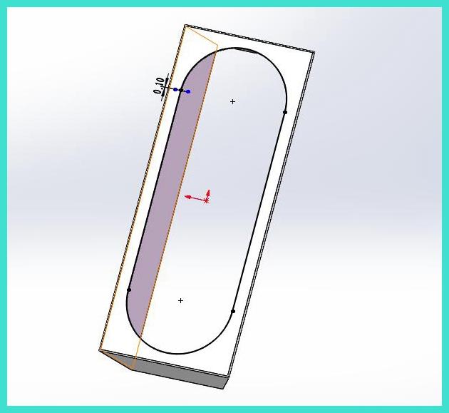
17. Fac gapem in sketa referentia
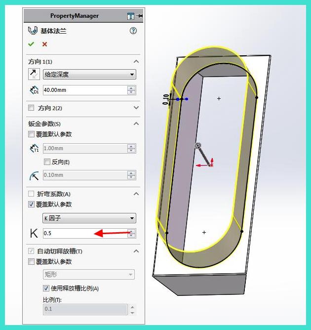
18. Click on [Base Flange] to set the depth. 40. Set the K factor to 0.5 to generate the base flange
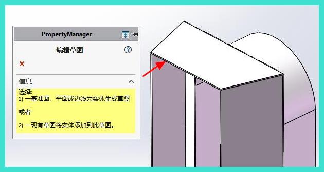
19. Click on [Sketch] to draw the sketch reference plane and select the plane indicated by the arrow
20. Draw a sketch of the base plate
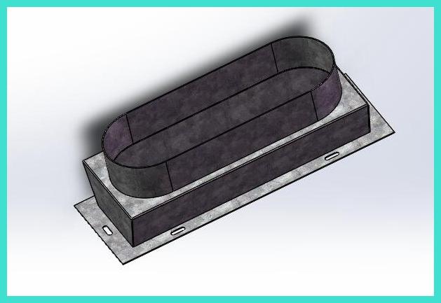
21. Click on [Base Flange] to generate the base plate
22. Rendering it
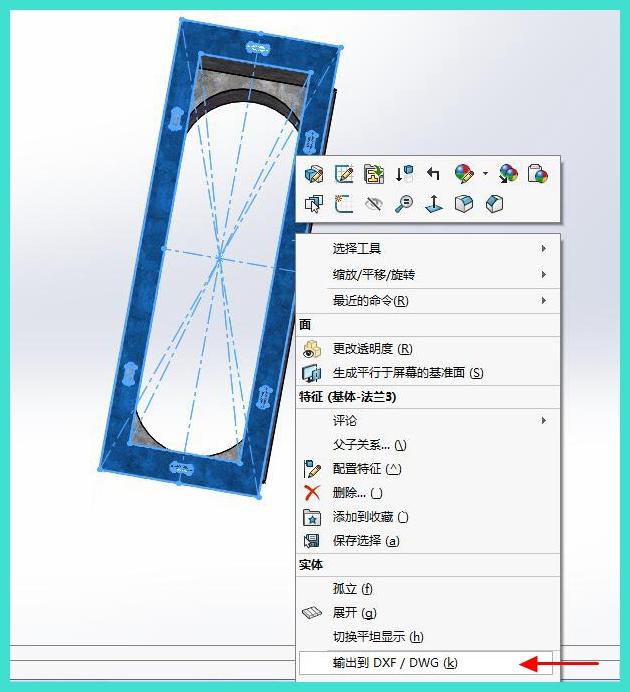
23. Select a face in the following image and click to expand it
24. Generate expansion
25. Click on the image below and click to expand
26. Generate expansion
27. Tablica funda non est parte fixa. Clicca dextera in panelo subter et clicca sagittam subter ut directe CAD generare