Germina vermica est typus germina quae verme mescetur et habet speciosum dentes profilum. Dentes vermiculorum sequitur generale a machina hobbing, prima duobus modis: hobbing et volantes sequitur. Recently, a friend questioned about how to adjust the installation angle and the precautions to be taken when machining worm gears with rolling cutters. Today, let's talk about this topic.
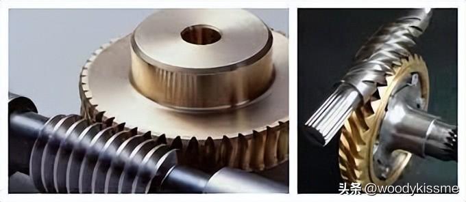
Cum fabricationem precisium fertilibus vermis, fertilibus fertilibus, fertilibus, aut fertilibus postquam fertilibus aut fertilibus succideris potest facere.
Hobbing gear 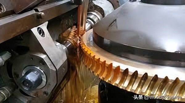
Using a worm gear rolling cutter with the same basic parameters as the working worm, the tooth profile is cut according to the principle of generating method. Si methodo radicalis fertilibus ad volandum fertilium utilizatur, rumpiter et rumpiter in paribus secundum transmissionem ratio Z 2/Z 1 (Z 1 est numerus fertilium in verme operationis, Z 2 est numerus dentium in rota wormatis), graduam accedent invicem usque distancia centra est distancia media quando rumpiter functionis vermis et rota wormatis. Ut modo fertilis tangentialis ad fertilibus, in addition to ensuring tool rotation, machina also needs to have axial feed; at the same time, the worktable of the machine tool also needs to increase corresponding additional rotation to achieve generating motion, which requires the use of differential chains. Therefore, the machining accuracy of tangential feed method is generally not as good as radial feed method, but the tooth surface quality is better and there will be no root cutting phenomenon. Precisio rotationis et cutationis fermentorum vermorum generale 6-8 nivellum attingere potest (JB162-60). The hobbing of precision worm gears requires the use of high-precision rolling cutters on high-precision indexing worm gear hobbing machines. Mechanical or electronic transmission chain error correction devices can also be installed on general-purpose hobbing machines to improve machining accuracy, with a maximum machining accuracy of up to level 3.
Flying Knife Cutting Teeth 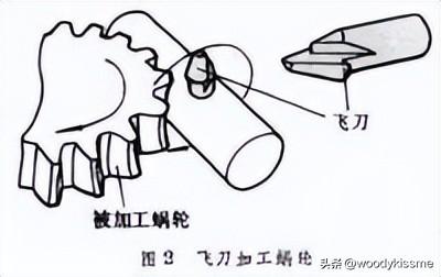
culter volans equivalent denti calciarii vermiculi currantis. Cutus cultris fluentes solum foedus fertilis tangentialis utilizat. In machina fertilis culter fluentes unum revolutionem rotat potest et rota vermis dentem Z 1 rotat. In addition, the tangential feed of the flying cultro and the additional rotation of the worktable can also cut the correct dent profile according to the principle of unfolding method, with an accuracy of 7-8 levels. cultri volantes facile sunt fabricari, sed humiles productivitatem habent in dentibus secendi, facientes eos adequas ad utilizationem in singulis partes fabricatione et reparatione opus.
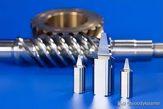
Parametri principali lapidis shaving cutor simili sunt quam vermis operis. Worm gear shaving is generally carried out using a hobbing machine, which can be driven by a shaving cutter to freely shave the worm gear teeth, or forcibly shave the teeth under the control of the machine tool transmission chain, resulting in improved tooth surface quality and accuracy after shaving.
After honing and grinding the worm gear dentes or cutting them with a flying cultro, in order to improve the quality of the tooth surface and the contact between the worm gear and the worm gear during meshing, honing or grinding can be carried out on the hobbing machine. Instrumentum fusionis est vermis fusionis faciens mixtura abrasii, plastici et resinus in substrato. In manibus gestionis, vermis fusionis ferreo ferreo faciens est ut pulserat rotam vermis in abrasio.
Ex supra sunt diversa metodes processionis fertilibus vermis. Thema hodie est: quomodo install are fertilibus fertilibus fertilibus fertilibus fertilibus fertilibus fertilibus, et quid difficiles attention cum rollerint et secerint:
Roll cutting worm gear 1. Ordinary worm gear rolling cutter
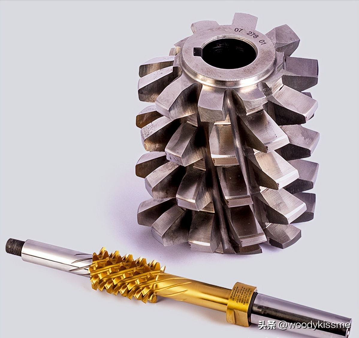
Usually, when processing worm gear, the basic worm gear of the standard worm gear rolling cutter (hereinafter referred to as the rolling cutter) used conforms to the working worm gear that meshes with the processed worm gear. Its main parameters, such as modulus, pressure angle, pitch circle diameter, numera capita, spiral direction, et spiral rise angle, consistent with the meshing worm shaft. Moreover, in processing worm gear, machinmachina centre distantia rolling cutter est similis a distantia operum, ita ut machinmachina worm gear pertransierunt in medium locum, sic in quo periculum periculum periculum est.m gear can theoretically ensure correct meshing with the worm gear.
When a regular rolling cutter rolls a worm gear, the rolling cutter is in the working position of the working worm gear, i.e. the tool is in a horizontal state and meshes with the worm gear in a positive staggered space. It slowly cuts inside a radial direction, and when it reaches the working center distance, the rolling dentes are completed and the worm gear rolling is finished.
2. Increased diameter worm gear rolling cutters (large outer diameter rolling cutters), but in actual production, it has been found that the worm gear meshing effect of traditional rolling cutters is often unsatisfactory, and the transmission torque is also difficult to meet the expected requirements. The development and use of increased diameter worm gear rolling cutters have solved this problem. Below is a brief introduction to the characteristics, basic design principles, and correct usage methods of the increased diameter worm rolling cutter.
The increased diameter worm gear rolling cutter adopts the local contact theory design, and the pitch circle diameter of the rolling cutter is slightly larger than the pitch circle of the working worm (non dual), so theoretically it is not a local contact, but a "point contact". However, during loading and use, due to elastic deformation, the point contact becomes a small local surface contact, and the contact surface is elliptical, thus meeting the requirement of concentrated meshing spots in the middle.
This point contact transmission overcomes the disadvantage of poor lubrication performance due to the instantaneous contact line of the contact gear pair being close to the relative velocity direction, thereby improving the transmission efficiency of the wheel system; On the other hand, a reduced sensitivity of transmission quality to manufacturing and installation errors of worm gear pairs, the requirements for manufacturing and installation accuracy of worm gear pairs are lowered. It also allows the worm gear rolling cutter to have more regrinding times, effectively extending the service life of the rolling cutter. In aliis casibus, circulus punctis armae vermis nimis parvus est, quod difficile facit fabricare calumniam et habet pauperem fortitudinem. Increasing diameter potest solure hoc problemam et facit manufacturam calumniarum.
3. Principulus design of the increased diameter worm rolling gear cutter is based on the meshing principle of helical gear s, so that the normal base joint of the rolling cutter's basic worm is equal to that of the working worm. Postquam diametrum cresceret, angulus normal is pressionis in circulo punctis vermis rotationis inmutatus est, similis quam vermis operantis, numerus capitum inmutatus est, et modulus normalis duorum est idem.
In general, the percentage increase of the dividing circle is selected first, and the selection of diameter increase is usually based on experiments and experience. Dimensio eius relata est ad typum germinae vermis processi et granditudinem regionis contactorum. Generalis, quando germina vermis singula capita est, maxima valor accipit, et quando multi capita est, minor valor accipit. Certem, etiam calculum potest, sed calculus est relative complexus.
The relationship between the increase in diameter and the contact area of 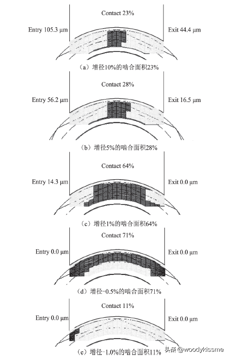
Generally speaking, the increase in diameter is relatively large, and based on experience, it is possible to achieve a 20% or even more increase in diameter. Calculate the increase in diameter according to this requirement.
Given: worm gear m x, α x (α n), d (r), λ, n (where m is the modulus, α is the pressure angle, d is the pitch circle diameter, r is the radius, λ is the thread angle, and n is the number of heads), and worm gear width b2. omnis subscriptus qui continet 'o' in symbolo indicat instrumentum succutionis, cum omnis subscriptus sine 'o' indicat instrumentum functionis vermis; The subscript x represents the axial direction, n represents the normal direction, and 2 represents the worm gear.
Anglo Spiralis vermis: β=90- λ
si incrementatio radii calcatoris voluptatis Fr est et radius calcatoris calcatoris calcatoris post crescentiam diametri ro est
ro=r+Fr
cos βo=rcos(β)/ro
mxo=mxsinβ/sinβo
The corresponding increment of center distance during gear hobbing is:
ΔA=Fr
Anglus Installationis gearis hobbing: SA=β 0- β
Postquam calcator rursum in clypeo repletus est, angulum installation is recalculatum est propter diminutionem diametri exterioris calcatoris rursus. Usually, the design of rolling cutters takes into account the issue of grinding. So in the design process, an additional value Δ r (grinding capacity, usually around 0.1M) will be added on the top of the previous one. At this point:
ro'=ro+Δr
do'=2ro'
tan βo'=tan(βo)(ro+Δr)/ro
λo'=90-βo'
ΔA'=Fr+Δr
At this point, the installation angle should be: SA&# 39= β-βo'
4. Secundo supra principibus design, differentia maxima inter crescentem pelliculam calorium calorium diameter is et calorium caloris caloris caloris caloris diameteris non est amplius aequa illo originalis pelliculae, sed paululum minor quam illo originalis pelliculae vermis; Lingua etiam versa est a valore originale.
Structural differences between increased diameter worm gear cutters and traditional worm gear cutters

Differences in the use of increased diameter worm gear cutters and traditional worm gear cutters

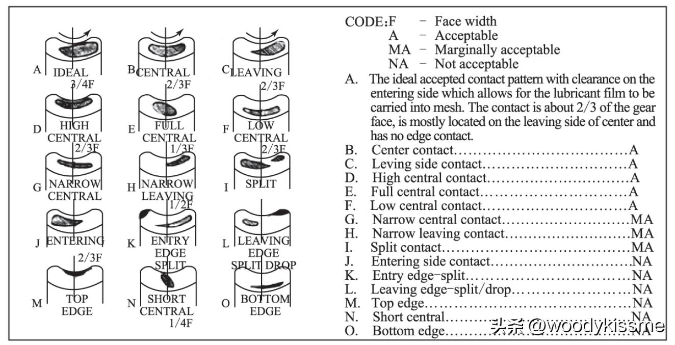
5. Instructions for using the increased diameter worm gear rolling cutter: Due to the fact that the thread angle of the increased diameter worm gear rolling cutter is no longer equal to the thread angle of the working worm gear, the knife is no longer horizontal when machining the worm gear, but needs to be adjusted by a small installation angle (pay attention to the direction). Distancia germinatorum intermediae non est aequa distanciae intermediae ecclesiae, sed paululum maior quam distancia intermediae ecclesiae. After grinding, the diameter of the blade becomes smaller and the parameters change, resulting in changes in the above items during each rolling process. Therefore, when using an increased diameter rolling cutter to machine worm gears, it is necessary to detect the contact points on the first worm gear. Based on the condition of the contact points, the installation angle of the rolling cutter can be adjusted to ensure that the contact points of the worm gear are in the middle of the worm gear before officially starting to process the worm gear, in order to achieve the expected effect.
Ut certem quod angulum calices gearis vermis processus a crescente calicero diametro rullens conformetur in requiribus drawingis, tener calicero rullens rotaturus est angulo quando installatur maximus calicer rullens diametros. As for how these process parameters change, generally tools suppliers will provide a parameter adjustment table.
Attention: (1) After grinding the tool, it is necessary to re-measure the external diameter value of the rolling cutter.
(2) Ensure correct installation angle and center distance.
(3) Observe the meshing points and adjust the installation angle in a timely manner.
Si hoc articulum tibi adiuvavit, date illum similem. Gratias tibi!
I am Woodykissme, and I regularly share content related to mechanical transmission and gear processing. If you are interested in this area, please follow me. Spero loqui cum omnibus:
The design and processing methods of gears, as well as related issues regarding the design, manufacturing, and use of cutting tools used for gear processing.
Design and calculation methods for gear cutting tools, development of related application programs, CAD secondary development and automatic drawing related technical issues. In terms of tool application, the cutting parameters, coatings, and service life of the tool, as well as the problems encountered during machining and their solutions.


 English
 Spanish
 Arabic
 Portuguese
 Belarusian
 Japanese
 Russian
 Icelandic
 Bulgarian
 Azerbaijani
 Estonian
 Irish
Irish Polish
 Persian
 Boolean
 Danish
 German
 French
 Filipino
 Finnish
 Korean
 Dutch
Dutch Galician
 Catalan
 Czech
Czech Croatian
 Latvian
 Romanian
 Maltese
 Malay
Malay Macedonian
 Norwegian
 Swedish
 Serbian
 Slovak
 Slovenian
 Swahili
 Thai
Thai Turkish
 Welsh
Welsh Urdu
Urdu Ukrainian
 Greek
Greek Hungarian
 Italian
 Yiddish
 Indonesian
 Vietnamese
 Haitian Creole
 Spanish Basque


