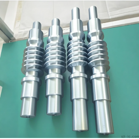
In order to ensure that the machining of the spline shaft can be completed on the precision turning machining center, a "one top, one clamp" clamping method is adopted according to its structural characteristics. The fourth axis indexing head of the precision turning machining center is added, and the keyway is milled according to certain process requirements. Due to the complexity of the entire part process, this article only elaborates on the content related to milling rectangular splines. 1、 Analysis of processing methods

The workpiece material is 40Cr, and the precision turning performance is good. Before CNC milling, all parts of the workpiece, except for the spline part, have been cut and processed, including 2 reference holes.
When milling rectangular splines, a "one top, one clamp" positioning installation can be used. The key to machining the rectangular spline of this part on a precision turning machining center is to solve the indexing problem when milling the rectangular key. The CNC universal indexing head configured on the precision turning machining center can be used. When the workpiece rotates at a certain angle, after the positioning of the end mill is completed, it runs parallel to the axial direction of the workpiece once. The workpiece rotates sequentially, and the end mill moves axially in sequence. After multiple cycles, a rectangular spline can be milled. In precision turning machining, macro program programming and subroutine calling can be used to reduce the shortcomings of excessively long CNC Machining programs.
2、 Processing process and related macro programs
To improve cutting efficiency, a large diameter milling cutter is selected as much as possible. Due to the narrow keyway, according to the size requirements of the process drawing, a solid carbide end milling cutter with a diameter of 8mm is selected.
Adopting a "one top, one clip" positioning installation. Install the tailstock and universal indexing head on the milling machine, and install the workpiece between the tailstock and universal indexing head.
Due to the fact that the maximum contour depth during keyway milling is only about 3mm, milling can be carried out by lowering the tool once to the groove contour depth, with a spindle speed of 1500 r/min and a feed rate of 150mm/min. Due to the fact that the cutting amount for the first pass of each keyway is the maximum, it can be slightly slower; In order to achieve high efficiency, the feed rate can be increased for other tool passes.
For the convenience of tool alignment and programming, the origin of the workpiece coordinate system is set at the left end axis of the workpiece spline axis shown in Figure 1. For ease of explanation, assuming that milling starts from the left side of the milling keyway and continues until the right side of the milling keyway, the workpiece rotates counterclockwise by indexing. The entire milling process of a keyway is divided into the following stages:
(1) Left side of milling key Kai

The initial position when milling the left side of the keyway, where the left side of the keyway is in a vertical position, as shown in Figure 4. The coordinate of the tool position is Z=2l * arccosl1=20.616; Y=8/2+8/2=8。 Milling the entire spline along the X-axis with a milling cutter
(2) Rotate the bottom left corner of the keyway to the top position

Due to the use of a flat bottomed end mill, when the workpiece is turned counterclockwise from the initial position 11 to the position shown in Figure 5, if milling is required, only the lower left corner of the end mill can be used for milling. The milling amount is too small, so this process is not milling, and the workpiece only rotates in place. At this point, the coordinate value of the cutting point is Z=21; Y=4。
(3) Slot bottom milling process
Due to the use of a flat bottomed end mill, when the workpiece continues to rotate counterclockwise from position 5 to position 6, the milling position of the end mill gradually transitions from the bottom left corner of the tool to the middle position at the bottom of the tool shown in Figure 6 for milling.
To avoid interference between the tool and the workpiece, the tool position must change as the workpiece rotates. The Z-coordinate value of the cutting point is 21mm; The Y value varies with the rotation of the workpiece. Change from Y=4 to Y=-4.
When the workpiece continues to rotate counterclockwise from position 6 to the bottom right corner of the keyway in Figure 7, which is directly above it, the milling position of the end mill gradually transitions from the middle position at the bottom to the bottom right corner position shown in Figure 7 for milling. At this point, the coordinate value of the cutting point Z=2I; Y= 4。
The entire process involves turning the workpiece through 23. At each small angle, the milling cutter mills the entire bottom of the spline groove along the X-axis.
(4) Turn the empty right side of the keyway to the vertical position
During the process of turning the workpiece counterclockwise from position 7 to the position shown in Figure 8, if milling is required, only the side edge at the bottom right corner of the end mill needs to be slightly milled. The milling amount is too small, so this process is not milled, and the workpiece only rotates in place.

(5) Milling the right side of the keyway, and finally milling the right side of the keyway. At this time, the right side of the keyway is in a vertical position, and the coordinate of the tool position is Z=21arccos11=20.616; Y=-8.
The milling cutter cuts the entire right side of the spline groove along the X-axis direction.
During the entire machining process from Figure 4 to Figure 8, except for the groove bottom milling process, all other stages can be completed with a simple GO1 command. So the following will only provide some explanations for the macro program of slot bottom milling.
In the process of milling the bottom of the slot, assuming that the workpiece only rotates counterclockwise, the total rotation of each keyway bottom is only 2, and the total displacement in the Y direction is 8. Therefore, the approximate relationship between the rotation angle θ and the displacement Y is obtained

Here, a macro program is written using the FANUC Series Oi-MODELD numerical control system in the mechanical factory. The origin of the workpiece coordinate system is set at the left end of the spline axis shown in Figure 1. The following is an example of a slot bottom milling macro program:
In order to ensure that the machining of the spline shaft can be completed on the precision turning machining center, a "one top, one clamp" clamping method is adopted according to its structural characteristics. The fourth axis indexing head of the precision turning machining center is added, and the keyway is milled according to certain process requirements.


 Spanish
 Arabic
 French
 Portuguese
 Belarusian
 Japanese
 Russian
 Malay
Malay Icelandic
 Bulgarian
 Azerbaijani
 Estonian
 Irish
Irish Polish
 Persian
 Boolean
 Danish
 German
 Filipino
 Finnish
 Korean
 Dutch
Dutch Galician
 Catalan
 Czech
Czech Croatian
 Latin
Latin Latvian
 Romanian
 Maltese
 Macedonian
 Norwegian
 Swedish
 Serbian
 Slovak
 Slovenian
 Swahili
 Thai
Thai Turkish
 Welsh
Welsh Urdu
Urdu Ukrainian
 Greek
Greek Hungarian
 Italian
 Yiddish
 Indonesian
 Vietnamese
 Haitian Creole
 Spanish Basque

