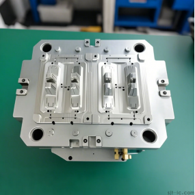
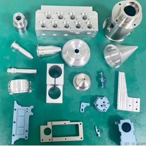
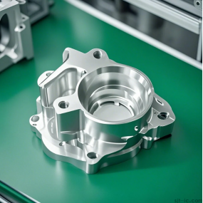
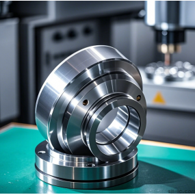
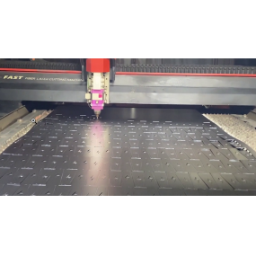
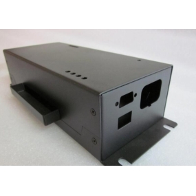
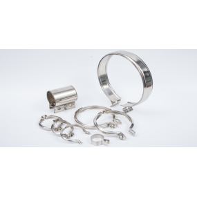
The main content of the preparation stage for CNC Machining is CNC programming, which usually includes analyzing part drawings and determining the machining process; Calculate the tool path and obtain the tool position data; Write CNC machining programs; Create control media; Proofreading program and first piece trial cutting. There are two methods: manual programming and automatic programming. In short, it is the entire process from part drawings to obtaining CNC machining programs.
Manual programming
definition
Manual programming refers to all stages of programming being completed manually. Using general calculation tools and various trigonometric function calculation methods, manually perform tool trajectory calculations and program instructions.
This method is relatively simple, easy to master, and has great adaptability. Used for non mold processed parts.
Programming steps
CNC process for manually completing part machining
Analyze part drawings
Making process decisions
Determine the processing route
Select process parameters
Calculate tool path coordinate data
Write CNC machining program sheet
Verification Program
Manual programming
Tool path simulation
advantage
Mainly used for point machining (such as drilling, reaming) or machining parts with simple geometric shapes (such as flat or square grooves), with small computational complexity, limited program segments, and intuitive and easy to implement programming.
shortcoming
For parts with spatial free surfaces and complex cavities, tool trajectory data calculation is quite cumbersome, requires a large amount of work, is prone to errors, and is difficult to proofread, some of which may even be impossible to complete.
automatic programming
edit
definition
For geometrically complex parts, it is necessary to use a computer to write the part source program in a specified CNC language, and after processing, generate a machining program, which is called automatic programming.
With the development of CNC technology, advanced CNC systems not only provide users with general preparation and auxiliary functions for programming, but also provide a means to expand CNC functions for programming. The parameter programming of FANUC6M CNC system is flexible in application and free in form, with expressions, logical operations, and similar program flows in high-level computer languages, making the machining program concise and easy to understand, and achieving functions that are difficult to achieve with ordinary programming.
CNC programming, like computer programming, also has its own"a; Language;, But one difference is that computers have now developed to dominate the global market with Microsoft's Windows as the absolute advantage. CNC machine tools are different. They have not yet developed to the level of mutual universality, which means that their hardware differences have made their CNC systems unable to achieve mutual compatibility. Therefore, when I want to process a blank, the first thing I need to do is to consider what model of system we already have for our CNC machine tools
Common software
⑴UG
Unigraphics is a set of three-dimensional parametric software developed by Unigraphics Solution in the United States, which integrates CAD, CAM, and CAE functions. It is the most advanced computer-aided design, analysis, and manufacturing high-end software today, used in industrial fields such as aviation, aerospace, automobiles, ships, general machinery, and electronics.
UG software is in a leading position in the field of CAM, originated from McDonnell Douglas Aircraft Company in the United States, and is the preferred programming tool for CNC machining of aircraft parts.
Advantages of UG
Provide reliable and accurate tool paths
Can be directly machined on surfaces and solids
A good user interface, and customers can also customize the interface with a variety of processing methods, making it easy to design and combine efficient tool paths
Complete tool library
Processing parameter library management function
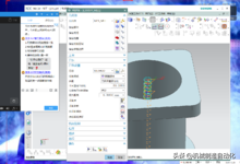
Including 2-axis to 5-axis milling, lathe milling, and wire cutting
Large tool library management
Solid simulation cutting
Universal post-processor and other functions
High speed milling function
CAM Customization Template
⑵Catia
Catia is a product launched by French company Dassault, and is used in the development and design of the Phantom series fighter jets, Boeing 737, and 777.
CATIA has powerful surface modeling capabilities and ranks among the top in all CAD 3D software. It is widely used in domestic aerospace enterprises and research institutes, gradually replacing UG as the preferred choice for complex surface design.
CATIA has strong programming capabilities and can meet the CNC machining requirements of complex parts. Some fields adopt CATIA design modeling and UG programming processing, combining the two and using them together.
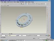
⑶ Pro/E is
The software developed by PTC (Parameter Technology Co., Ltd.) in the United States is the most popular 3D CAD/CAM (Computer Aided Design and Manufacturing) system in the world. Widely used in civilian industries such as electronics, machinery, molds, industrial design, and toys. It has multiple functions such as part design, product assembly, mold development, CNC machining, and shape design.
Pro/E is widely used in enterprises in southern China, and it is common practice to use PRO-E for design modeling and MASTERCAM and CIMATRON for programming and processing.
Pro/E
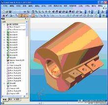
⑷Cimatron
The Cimatron CAD/CAM system is a CAD/CAM/PDM product of Israel's Cimatron company. It is one of the earliest systems to achieve full functionality of 3D CAD/CAM on a microcomputer platform. The system provides a relatively flexible user interface, excellent 3D modeling, engineering drawing, comprehensive CNC machining, various universal and specialized data interfaces, and integrated product data management. The Cimatron CAD/CAM system is highly popular in the international mold manufacturing industry, and is also widely used in the domestic mold manufacturing industry.
Cimatron (2 sheets)
⑸Mastercam
A PC based CAD/CAM software developed by CNC Corporation in the United States. Mastercam provides an ideal environment for designing the shape of parts with convenient and intuitive geometric modeling. Its powerful and stable modeling functions can design complex curved and curved parts. Mastercam has strong functions in surface rough machining and surface precision machining. There are multiple options for surface precision machining, which can meet the surface machining requirements of complex parts, and it also has multi axis machining function. Due to its low price and superior performance, it has become the preferred CNC programming software in the domestic civil industry.
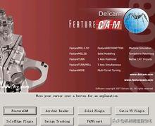
⑹FeatureCAM
The feature based fully functional CAM software developed by DELCAM in the United States features a new concept of features, strong feature recognition, material library based on process knowledge base, tool library, and icon navigation based on process card programming mode. A fully modular software that provides comprehensive solutions for workshop programming, from 2-5 axis milling, to turning milling composite machining, from surface machining to wire cutting machining. The post editing function of DELCAM software is relatively good.
Some domestic manufacturing enterprises are gradually introducing new products to meet the needs of industry development.
FeatureCAM (2 sheets)
CAXA Manufacturing Engineer
CAXA Manufacturing Engineer is a nationally produced CAM product launched by Beijing Beihang Haier Software Co., Ltd., which has helped domestic CAM software occupy a place in the domestic CAM market. As an excellent representative and well-known brand of independent intellectual property software in the field of information technology in China's manufacturing industry, CAXA has become a leader and major supplier in the Chinese CAD/CAM/PLM industry. CAXA Manufacturing Engineer is a milling/drilling CNC machining programming software with good process performance for two to five axis CNC milling machines and machining centers. This software has superior performance, moderate price, and is quite popular in the domestic market.
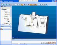
⑻EdgeCAM
A professional CNC programming software with intelligence produced by Pathtrace company in the UK, which can be applied to
EdgeCAM
Programming of CNC machine tools such as turning, milling, and wire cutting. EdgeCAM has designed a more convenient and reliable machining method for the current complex three-dimensional surface machining characteristics, which is popular in the manufacturing industry in Europe and America. British Pathway Company is currently developing and operating in the Chinese market, providing more choices for domestic manufacturing customers.
⑼VERICUTVERICUT
An advanced specialized CNC machining simulation software produced by CGTECH in the United States. VERICUT adopts advanced 3D display and virtual reality technology, achieving extremely realistic simulation of CNC machining processes. Not only can colored 3D images be used to display the cutting tool cutting blanks to form parts
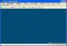
VERICUTVERICUT
The entire process can also display the tool handle, fixture, and even the operation process of the machine tool and the virtual factory environment can be simulated, and the effect is like watching a video of a CNC machine tool machining parts on the screen.
Programmers import various CNC machining programs generated by programming software into VERICUTVERICUT for verification, which can detect calculation errors generated in the original software programming and reduce the machining accident rate caused by program errors during machining. At present, many strong domestic enterprises have begun to introduce this software to enrich their existing CNC programming systems and have achieved good results.
With the rapid development of manufacturing technology, the development and use of CNC programming software have entered a new stage of rapid development. New products are emerging one after another, and functional modules are becoming increasingly refined. Process personnel can easily design scientifically reasonable and personalized CNC machining processes on microcomputers, making CNC machining programming easier and more convenient.
(10)PowerMill
PowerMILL is a powerful CNC machining programming software system produced by Delcam Plc in the UK, with rich machining strategies. Adopting a brand new Chinese WINDOWS user interface, providing comprehensive processing strategies. Helping users generate the best machining solution, thereby improving machining efficiency, reducing manual trimming, and quickly generating rough and fine machining paths. Any modification and recalculation of the solution is almost completed in an instant, reducing 85% of the tool path calculation time. This enables complete interference inspection and elimination of 2-5 axis CNC machining, including tool holders and tool holders. Equipped with integrated machining entity simulation, it facilitates users to understand the entire machining process and results before machining, saving machining time.

Basic steps
1. Analyze part drawings to determine the process flow
Analyze the shape, size, accuracy, material, and blank required by the part drawing, and clarify the processing content and requirements; Determine the machining plan, cutting route, cutting parameters, and select cutting tools and fixtures.
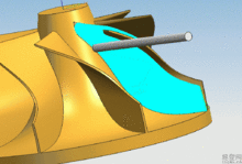
Knife path (3 sheets)
2. Numerical calculation
Calculate the starting and ending points of geometric features on the part contour, as well as the center coordinates of arcs, based on the geometric dimensions of the part, processing route, and other factors.
3. Write processing programs
After completing the above two steps, write the machining program according to the functional instruction code and program segment format specified by the CNC system.
4. Input the program into the CNC system
The program input can be directly entered into the CNC system through the keyboard or through a computer communication interface.
Inspection procedures and first piece cutting
Use the graphic display function provided by the CNC system to check the correctness of the tool path. Perform first piece trial cutting on the workpiece, analyze the causes of errors, and make timely corrections until qualified parts are cut.
Although the programming language and instructions of each CNC system are different, there are also many similarities between them
Function code
edit
Characters and their functions
1. Characters and codes
Characters are symbols used to organize, control, or represent data, such as numbers, letters, punctuation, mathematical operators, etc. There are two widely used standard codes internationally:
1) ISO International Organization for Standardization Standard Code
2) EIA Electronic Industries Association of America Standard Code
Two characters
In CNC machining programs, characters refer to a series of characters arranged according to regulations, stored, transmitted, and operated as an information unit. A character is composed of an English letter followed by several decimal digits, and this English letter is called an address character.
For example, "X2500" is a word, X is the address symbol, and the number "2500" is the content of the address. In the FANUC system, if the value in the address has a decimal point, it represents millimeter units; if it does not have a decimal point, it represents micrometer units. For example, X2500 X coordinate 2500 millimeters (X2500 represents X coordinate 2500 micrometers)
3. The function of characters
Each word that constitutes a program segment has its specific functional meaning, and the following is mainly introduced based on the specifications of FANUC-0M CNC system.
(1) Serial number N
Sequence number, also known as program segment number or program segment number. The sequence number is located at the beginning of the program segment and consists of the sequence number N and subsequent digits. Its functions include proofreading, conditional jumps, fixed loops, etc. When using, it should be used at intervals, such as N10 N20 N30... (The program number is only for marking purposes and has no actual meaning)
⑵ Prepare functional word G
The address symbol for preparing function words is G, also known as G function or G instruction, which is an instruction used to establish the working mode of a machine tool or control system. G00~G99
⑶ Size words
The dimension word is used to determine the coordinate position of the end point of tool movement on the machine tool.
Among them, the first group X, Y, Z, U, V, W, P, Q, R is used to determine the linear coordinate dimensions of the endpoint; The second group A, B, C, D, E are used to determine the angular coordinate dimensions of the endpoint; The third group I, J, and K are used to determine the center coordinate size of the arc contour. In some CNC systems, P instruction can also be used to pause time, and R instruction can be used to determine the radius of the arc.
(4) Feed function word F
The address symbol of the feed function word is F, also known as F function or F instruction, used to specify the feed rate for cutting. For lathes, F can be divided into two types: feed per minute and spindle feed per revolution. For other CNC machine tools, feed per minute is generally only used. The F instruction is commonly used in thread cutting program segments to indicate the lead of the thread.
Main spindle speed function word S
The address symbol of the spindle speed function word is S, also known as S function or S command, used to specify the spindle speed. The unit is r/min.
Tool function word T
The address symbol of the tool function word is T, also known as T function or T instruction, used to specify the number of tools used during machining, such as T01. For CNC lathes, the following numbers are also used for specified tool length compensation and tool tip radius compensation, such as T0101.
Auxiliary function word M
The address symbol of the auxiliary function word is M, and the subsequent digits are generally positive integers of 1-3 bits, also known as M function or M instruction, used to specify the switch action of the auxiliary device of the CNC machine tool, such as M00-M99.
Program Format
edit
Program segment format
A CNC machining program is composed of several program segments. Program segment format refers to the arrangement of words, characters, and data in a program segment. Example of program segment format:
N30 G01 X88.1 Y30.2 F500 S3000 T02 M08;
N40 X90; This program segment omits the continuation word "G01.", Y30.2,F500,S3000,T02,M08”, But their functions are still effective
In the program segment, it is necessary to clearly define the various elements that make up the program segment:
Moving target: endpoint coordinates X, Y, Z;
Moving along what trajectory: Prepare the function word G;
Feed rate: feed function word F;
Cutting speed: spindle speed function letter S;
Using tools: Tool function letter T;
Machine tool auxiliary action: auxiliary function word M.
Program Format
1) Program start and end symbols
The starting and ending symbols of the program are the same character, with% in ISO code and EP in EIA code. When writing, a single column segment should be used.
2) Program Name
There are two forms of program names: one is composed of the English letter O (% or P) and 1-4 positive integers; Another type is a program name that starts with an English letter and is composed of a mixture of letters, numbers, and multiple characters (such as TEST 1). Generally, a separate section is required.
3) Program subject
The program body is composed of several program segments. Each program segment usually occupies one line
4) Program End
The program can be completed using the M02 or M30 instruction. Generally, a separate section is required.
Examples of general formats for machining programs:
%//Start symbol
O2000//Program name
N10 G54 G00 X10.0 Y20.0 M03 S1000//Program body
N20 G01 X60.0 Y30.0 F100 T02 M08
N30 X80.0
…… .
N200 M30//Program ended
%//End symbol
Machine tool coordinates
edit
Determine the coordinate system
(1) Regulations on relative motion of machine tools
On machine tools, we always assume that the workpiece is stationary while the tool is in motion. In this way, programmers can determine the machining process of the machine tool based on the part drawing without considering the specific movement of the workpiece and tool on the machine tool
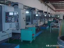
machining center
⑵ Regulations on the coordinate system of machine tools
The relationship between the X, Y, and Z coordinate axes in the standard machine coordinate system is determined by the right-hand Cartesian Cartesian coordinate system.
On a CNC machine tool, the motion of the machine tool is controlled by the CNC device. In order to determine the forming motion and auxiliary motion on the CNC machine tool, it is necessary to first determine the displacement and direction of the motion on the machine tool. This needs to be achieved through a coordinate system, which is called the machine tool coordinate system.
For example, on a milling machine, the longitudinal, transverse, and vertical movements of an organic bed. In CNC machining, machine coordinate systems should be used to describe it.
The relationship between the X, Y, and Z axes in the standard machine coordinate system is determined by the right-hand Cartesian Cartesian coordinate system:
1) Extend the thumb, index finger, and middle finger of your right hand, making them 90 degrees apart. The thumb represents the X coordinate, the index finger represents the Y coordinate, and the middle finger represents the Z coordinate.
2) The thumb points in the positive direction of the X coordinate, the index finger points in the positive direction of the Y coordinate, and the middle finger points in the positive direction of the Z coordinate.
3) The rotation coordinates around the X, Y, and Z coordinates are represented by A, B, and C. According to the right-hand spiral rule, the direction of the thumb is the positive direction of any axis in the X, Y, and Z coordinates, and the rotation direction of the other four fingers is the positive direction of the rotation coordinates A, B, and C.
⑶ Regulations on the direction of movement
The direction of increasing the distance between the tool and the workpiece is the positive direction of each coordinate axis. The following figure shows the positive directions of two movements on a CNC lathe.
Coordinate axis direction
⑴ Z-coordinate
The direction of motion of the Z coordinate is determined by the spindle that transmits cutting power, that is, the coordinate axis parallel to the spindle axis is the Z coordinate, and the positive direction of the Z coordinate is the direction of the tool leaving the workpiece X coordinate
The X-coordinate is parallel to the clamping plane of the workpiece, usually within the horizontal plane. When determining the direction of the X-axis, two situations should be considered:
1) If the workpiece undergoes rotational motion, the direction of the tool leaving the workpiece is the positive direction of the X coordinate.
2) If the tool rotates, there are two situations: when the Z coordinate is horizontal, when the observer looks at the workpiece along the tool spindle, the+X direction of motion points to the right; When the Z coordinate is perpendicular, when the observer faces the tool spindle and looks towards the column, the+X direction of motion points to the right. The following figure shows the X coordinate of the CNC lathe.
⑶ Y coordinate
After determining the positive direction of the X and Z coordinates, the direction of the Y coordinate can be determined using the right-hand Cartesian coordinate system based on the direction of the X and Z coordinates.
Setting of Origin
The origin of a machine tool refers to a fixed point set on the machine tool, which is the origin of the machine coordinate system. It has been determined during the assembly and debugging of the machine tool, and is the reference point for the machining motion of the CNC machine tool.
(1) Origin of CNC lathe
On a CNC lathe, the origin of the machine tool is generally taken at the intersection of the chuck end face and the centerline of the spindle. Meanwhile, by setting parameters, the machine tool origin can also be set at the positive limit position of the X and Z coordinates.
⑵ Origin of CNC milling machine
The center of the lower end face of the spindle is at the forward limit position of the three axes.
Lathe programming
edit
For CNC lathes, different CNC systems have different programming methods.
Instruction for setting the workpiece coordinate system
It is an instruction that specifies the origin of the workpiece coordinate system, also known as the programming zero point.
Instruction format: G50 X Z
In the formula, X and Z are the dimensions in the X and Z directions from the starting point of the tool tip to the origin of the workpiece coordinate system.
When executing the G50 command, the machine tool does not move, that is, the X and Z axes do not move. The system remembers the values of X and Z internally, and the coordinate values on the CRT display change. This is equivalent to establishing a workpiece coordinate system with the workpiece origin as the coordinate origin within the system.
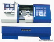
CNC lathe
Programming method for size system:
1. Absolute and incremental dimensions
In CNC programming, there are usually two ways to represent the coordinates of tool positions: absolute coordinates and incremental (relative) coordinates. When programming CNC lathes, absolute value programming, incremental value programming, or a combination of both can be used.
⑴ Absolute value programming: The coordinate values of all coordinate points are calculated from the origin of the workpiece coordinate system, called absolute coordinates, represented by X and Z.
⑵ Incremental value programming: The coordinate values in the coordinate system are calculated relative to the previous position (or starting point) of the tool, and are called incremental (relative) coordinates. The X-axis coordinates are represented by U, the Z-axis coordinates are represented by W, and the positive and negative are determined by the direction of motion.
2. Diameter programming and radius programming
When programming CNC lathes, due to the circular cross-section of the machined rotary parts, there are two ways to represent their radial dimensions: diameter and radius. The method used is determined by the system parameters. When CNC lathes leave the factory, they are generally set to diameter programming, so the size in the X-axis direction in the program is the diameter value. If radius programming is required, it is necessary to change the relevant parameters in the system to put it in a radius programming state.
3. Metric and English dimensions
G20 imperial size input G21 metric size input (Frank)
G70 imperial size input G71 metric size input (Siemens)
There are two forms of dimension annotation in engineering drawings: metric and imperial. The CNC system can convert all geometric values into metric or imperial dimensions using codes based on the set state. After the system is turned on, the machine tool is in metric G21 state.
The conversion relationship between metric and imperial units is:
1mm0.0394in
1in25.4mm
2、 Spindle control, feed control, and tool selection (FANUC-0iT system) 1. Spindle function S
The S function consists of an address code S and several digits following it.
⑴ Constant linear speed control command G96
After the system executes the G96 command, the value specified by S represents the cutting speed. For example, G96 S150 indicates that the cutting point speed of the turning tool is 150m/min.
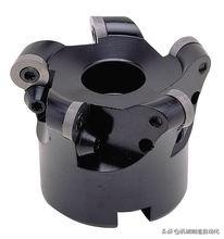
CNC tool
⑵ Cancel the constant linear speed control command G97 (constant speed command)
After the system executes the G97 command, the value specified by S represents the spindle speed per minute. For example, G97 S1200 represents a spindle speed of 1200r/min. After the FANUC system is turned on, it defaults to G97 state.
⑶ Maximum speed limit G50
In addition to the coordinate system setting function, G50 also has the function of setting the maximum spindle speed. For example, G50 S2000 means setting the maximum spindle speed to 2000r/min. When using constant linear speed control for cutting, in order to prevent accidents, it is necessary to limit the spindle speed.
2. Feed function F
The F function represents the feed rate, which is composed of an address code F and several subsequent digits.
⑴ Feed command G98 per minute
After executing the G98 command, the CNC system determines that the feed rate unit referred to by F is mm/min (millimeters/minute), such as G98 G01 Z-20.0 F200; The feed rate in the program segment is 200mm/min.
⑵ Feed command G99 per revolution
After executing the G99 command, the CNC system determines that the feed rate unit referred to by F is mm/r (millimeters/revolution), such as G99 G01 Z-20.0 F0.2; The feed rate in the program segment is 0.2mm/r.
Imputation instruction
(1) Quick positioning instruction G00
The G00 command enables the tool to quickly move from the point where the tool is located to the next target position through point positioning control. It is only for rapid positioning without any motion trajectory requirements and without any cutting process.
Instruction format:
G00 X(U)_ Z(W)_ ;
Among them:
X. Z is the absolute coordinate value of the point that the tool needs to reach;
U. W is the incremental value of the distance between the point to be reached by the tool and the existing position; (Non moving coordinates can be omitted)
2、 Linear interpolation instruction G01
The G01 command is a linear motion command that specifies the tool to perform any linear motion at a specified feed rate F through interpolation linkage between two coordinates.
Instruction format:
G01 X(U)_ Z(W)_ F_ ;
Among them:
(1) X, Z, or U, W have the same meaning as G00.
⑵ F is the feed rate (feed rate) of the tool, which should be determined according to the cutting requirements.
3、 Circular interpolation instructions G02 and G03
There are two types of circular arc interpolation commands: clockwise circular arc interpolation command G02 and counterclockwise circular arc interpolation command G03.
Programming format:
The command format for clockwise arc interpolation command is:
G02 X(U)_ Z(W)_ R_ F_;
G02 X(U)_ Z(W)_ I_ K_ F_;
The command format for counterclockwise arc interpolation command is:
G03 X(U)_ Z(W)_ R_ F_;
G03 X(U)_ Z(W)_ I_ K_ F_;
Among them:
⑴ X_Z_ is the absolute value of the endpoint coordinates for arc interpolation, and U_W_ is the incremental value of the endpoint coordinates for arc interpolation.
⑵ (radius method) R is the radius of an arc, expressed as a radius value.
When the center angle corresponding to the arc is 180, R is a positive value;
When the center angle corresponding to the arc is> At 180, R is a negative value.
⑶ (Center of Circle Method) I and K are the coordinate increments of the center of the circle relative to the starting point of the arc, expressed as the vectors along the X (I) and Z (K) axes.
(4) Selection principle: Choose the one that is more convenient to use (can be seen without calculation). When I, K, and R appear simultaneously in the same program segment, R takes priority (i.e. effective) and I and K are invalid.
When I is 0 or K is 0, it can be omitted and not written.
If you want to interpolate a whole circle, you can only use the center method to represent it, and the radius method cannot be executed. If two semicircles are connected by the radius method, the true roundness error will be too large.
F is the feed rate or feed rate along the tangent direction of the arc.
Professional Introduction
edit
Training objectives
To cultivate talents who can adapt to the needs of modern economic construction, have comprehensive development in morality, intelligence, and physical fitness, possess solid professional knowledge of CNC machine tool processing, strong hands-on ability, and be able to engage in CNC machining and CNC equipment operation and management in intelligent and skilled operation positions on the production line.
Main courses
Fundamentals of Mechanical Drawing, Tolerance Fit and Technical Measurement, Metal Materials and Heat Treatment, Mechanical Design Fundamentals, Engineering Mechanics, Hydraulic and Pneumatic Technology, Machine Tool Fixtures, Metal Cutting Principles and Tools, Mechanical Manufacturing Technology, Electrical and Electronic Fundamentals and Operation Skills, Fitter Skills Training CNC Lathe Processing Technology, CNC Milling Center Processing Technology, EDM Technology, AutoCAD, PRO/E 3D Modeling and Design, UG 3D Design and CNC Programming, MASTERCAM 3D Design and CNC Programming, CNC Machine Structure and Maintenance.
Employment direction
edit
Engaged in production management, mechanical product design, CNC programming and processing operations, CNC equipment installation, debugging and operation, CNC equipment fault diagnosis and maintenance, renovation, and after-sales service.
The first option is CNC operators. Students who have undergone CNC internships and CNC operation training can be competent, but the competition for this job position is the greatest. This major is available in any vocational college in engineering, not to mention students from vocational schools and technical schools. At present, the CNC operation positions in China's machining industry have basically reached saturation. Some students told me that their classmates, who graduated from junior high school and worked in CNC operations five or six years earlier than them, were already skilled workers with decent salaries, so they felt very hopeless. I told them that what needs to be compared is not the present, but the future development.
Secondly, a CNC programmer. Many machining enterprises use automatic programming to generate CNC machining programs, so they need to learn CAM software. Different units use different types of CAM software, but the processing methods are generally similar, so it is necessary to learn one well. However, as a CNC programmer, the requirements are high and the responsibility is also significant, so rich machining experience is required. In this case, it is not realistic for students who have just left the school to immediately take on this position. It must go through a period of exercise, ranging from one or two years to three to five years.
Thirdly, CNC maintenance personnel or after-sales service personnel. This position has higher requirements and is the most lacking in the field of CNC. Not only does it require rich mechanical knowledge, but also rich electrical knowledge. If you choose this direction, it may be very difficult (such as frequent business trips), and you need to constantly learn and accumulate experience. This position requires more training, so the time to become proficient will be longer, but the rewards will also be relatively generous.
Fourthly, CNC sales personnel. The salary for this position is the most generous, and the required professional knowledge is not so much, but it requires outstanding eloquence and good social skills, which are not something that ordinary people can do.
Fifth, similar majors can also be chosen: mechanical design professionals such as draftsmen, mechanical designers, and structural designers; Process management or on-site technical personnel, mechanical designers (mechanical engineers), CNC machine operators, mechanical equipment maintenance workers, mechanical equipment salespeople, programmers, mechanical process workers, inspectors, and production administrators.
Learning programming
edit
In the rapidly growing demand for CNC machining in the domestic manufacturing industry, there is a serious shortage of CNC programming technology talents, and CNC programming technology has become a hot demand in the job market.
Basic conditions that need to be met
(1) Possess basic learning abilities, that is, students have certain learning abilities and preparatory knowledge.
⑵ Have the conditions to receive good training, including selecting good training institutions and training materials.
Accumulate experience in practice.
Preparatory knowledge and skills
(1) Basic geometry knowledge (high school or above is sufficient) and mechanical drawing foundation.
Basic English.
⑶ General knowledge of mechanical processing.
Basic 3D modeling skills.
Select training materials
The content of the textbook should be suitable for the requirements of practical programming applications, with the widely adopted interactive graphic programming technology based on CAD/CAM software as the main content. While teaching practical techniques such as software operations and programming methods, it should also include a certain amount of basic knowledge, so that readers can understand the nature and reasons behind it.
The structure of the textbook. The learning of CNC programming technology is a process of continuous improvement in stages, so the content of textbooks should be allocated reasonably according to different learning stages. At the same time, systematically summarize and classify the content from an application perspective, making it easier for readers to understand and remember it as a whole.
Learning content and learning process
Stage 1: Basic knowledge learning, including basic knowledge of CNC machining principles, CNC programs, CNC machining processes, etc.
Phase 2: Learning CNC programming technology, with a preliminary understanding of manual programming, focusing on learning interactive graphic programming technology based on CAD/CAM software.
Stage 3: CNC programming and machining exercises, including a certain number of actual product CNC programming and machining exercises.
Learning methods and skills
Like learning other knowledge and skills, mastering the correct learning methods plays a crucial role in improving the efficiency and quality of learning CNC programming technology. Here are a few suggestions:
Concentrate on fighting the battle of annihilation, complete a learning goal in a short amount of time, and apply it in a timely manner to avoid marathon style learning.
⑵ Reasonably categorizing software functions not only improves memory efficiency, but also helps to grasp the overall application of software functions.
From the beginning, it is often more important to focus on cultivating standardized operating habits and a rigorous and meticulous work style, rather than simply learning technology.
Record the problems, mistakes, and learning points encountered in daily life, and this process of accumulation is the process of continuously improving one's level.
How to learn CAM
The learning of interactive graphic programming technology (also known as the key points of CAM programming) can be divided into three aspects:
1. When learning CAD/CAM software, the focus should be on mastering the core functions, because the application of CAD/CAM software also conforms to the so-called "20/80 principle", which means that 80% of applications only need to use 20% of its functions.
2. It is to cultivate standardized and standardized work habits. For commonly used machining processes, standardized parameter settings should be carried out and standard parameter templates should be formed. These standard parameter templates should be directly used in CNC programming of various products as much as possible to reduce operational complexity and improve reliability.
3. It is important to accumulate experience in processing technology, familiarize oneself with the characteristics of the CNC machine tools, cutting tools, and processing materials used, in order to make the process parameter settings more reasonable.
It should be pointed out that practical experience is an important component of CNC programming technology and can only be obtained through actual machining, which cannot be replaced by any CNC machining training textbook. Although this book fully emphasizes the combination of practice, it should be said that the changes in process factors generated in different processing environments are difficult to fully express in written form.
Finally, just like learning other technologies, we must achieve the goal of "disdaining the enemy strategically and valuing the enemy tactically". We must not only establish firm confidence in achieving our learning goals, but also approach every learning process with a down-to-earth attitude.


 Spanish
 Arabic
 French
 Portuguese
 Belarusian
 Japanese
 Russian
 Malay
Malay Icelandic
 Bulgarian
 Azerbaijani
 Estonian
 Irish
Irish Polish
 Persian
 Boolean
 Danish
 German
 Filipino
 Finnish
 Korean
 Dutch
Dutch Galician
 Catalan
 Czech
Czech Croatian
 Latin
Latin Latvian
 Romanian
 Maltese
 Macedonian
 Norwegian
 Swedish
 Serbian
 Slovak
 Slovenian
 Swahili
 Thai
Thai Turkish
 Welsh
Welsh Urdu
Urdu Ukrainian
 Greek
Greek Hungarian
 Italian
 Yiddish
 Indonesian
 Vietnamese
 Haitian Creole
 Spanish Basque

