Spanish
 Arabic
 French
 Portuguese
 Belarusian
 Japanese
 Russian
 Malay
Malay Icelandic
 Bulgarian
 Azerbaijani
 Estonian
 Irish
Irish Polish
 Persian
 Boolean
 Danish
 German
 Filipino
 Finnish
 Korean
 Dutch
Dutch Galician
 Catalan
 Czech
Czech Croatian
 Latin
Latin Latvian
 Romanian
 Maltese
 Macedonian
 Norwegian
 Swedish
 Serbian
 Slovak
 Slovenian
 Swahili
 Thai
Thai Turkish
 Welsh
Welsh Urdu
Urdu Ukrainian
 Greek
Greek Hungarian
 Italian
 Yiddish
 Indonesian
 Vietnamese
 Haitian Creole
 Spanish Basque

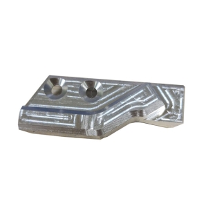
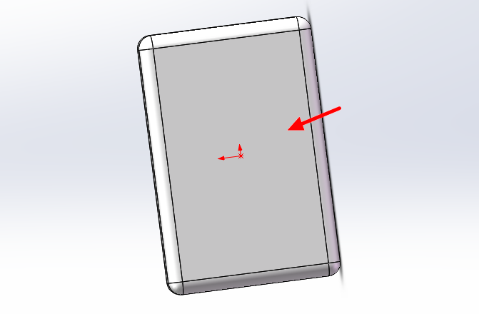
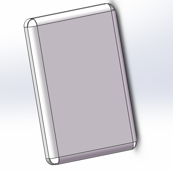
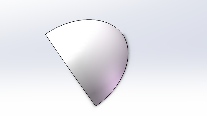
As shown in the figure below, it is a cover plate with 3 rounded corners. How to make this kind of rounded corner? Let me explain to everyone!
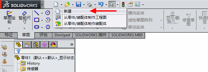
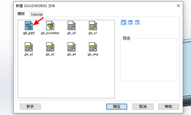
Open the Solid Works software and click on New
Select the part and click OK
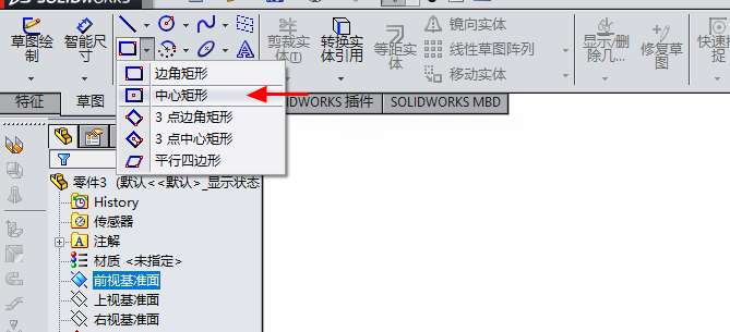
Select the reference plane, click on the sketch, and choose the center rectangle
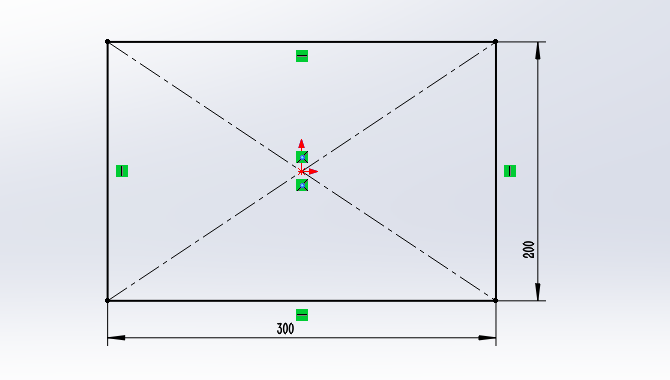
Draw the dimensions of the following diagram
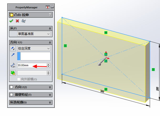
Click on stretch cutting, given a depth of 30mm
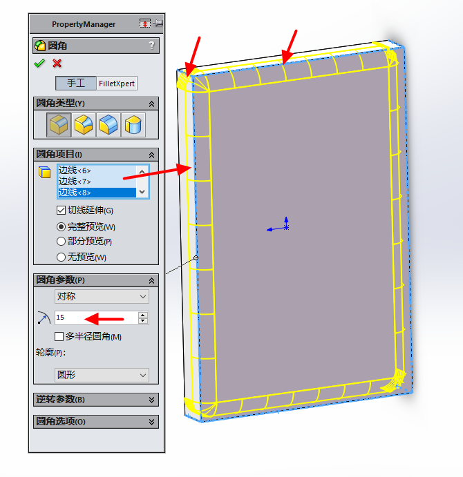
Click on the rounded corner
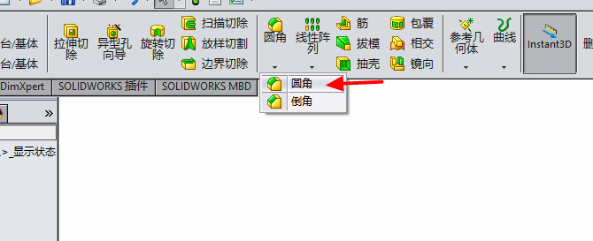
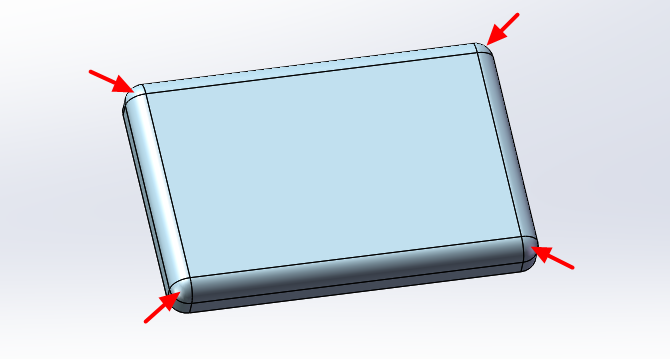
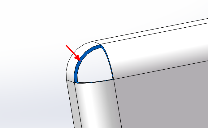
Select all blue edges of the arrows in the following image, with a chamfer radius of 15mm
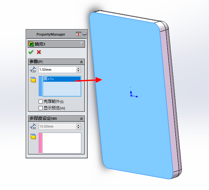
Click on the shell extraction button and set the shell extraction thickness to 1.5mm. The arrow indicates the surface to be removed.
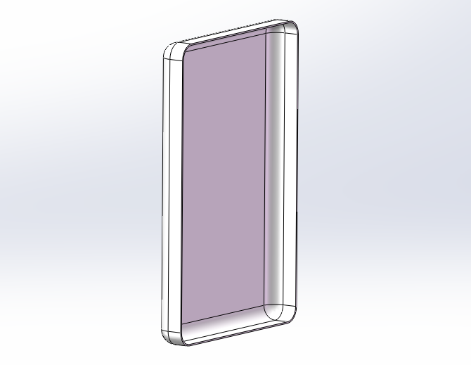
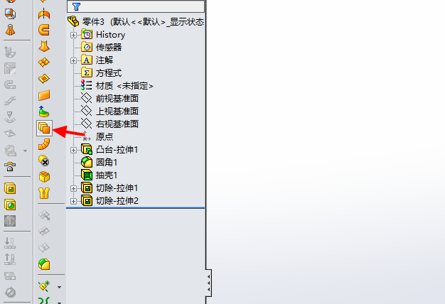
Generate solid parts
Draw a sketch of stretch cutting on the surface indicated by the arrow
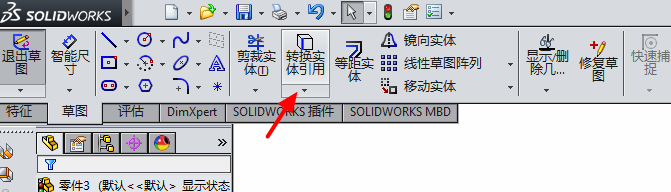
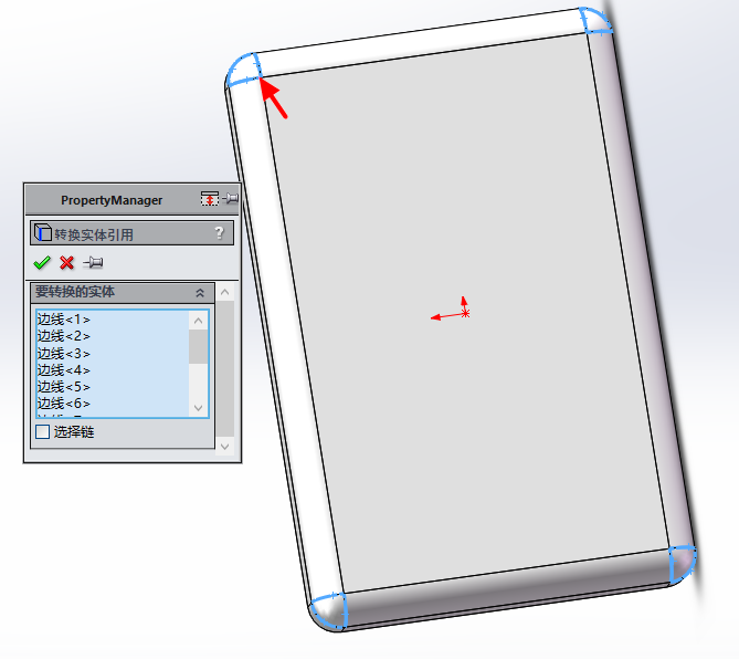
Click on entity conversion reference
Select the blue border at the four corners of the arrow
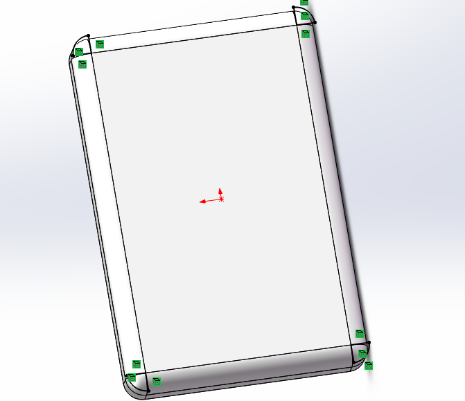
Quote sketch
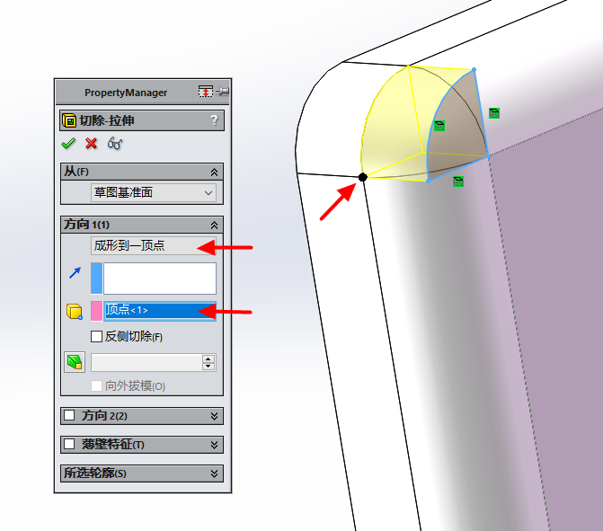
Click on stretch cutting, select to form to a vertex, and choose the point at the arrow
The effect after resection
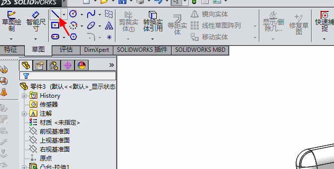
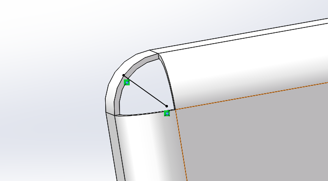
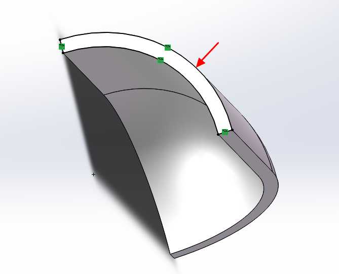
Click on the sketch and select the line
Select the surface shown in the following image
Draw a sketch
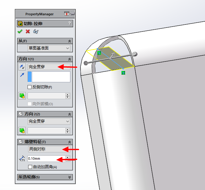
Click on stretch resection, select complete penetration, set thin-walled features, symmetrical on both sides, with a gap of 0.1
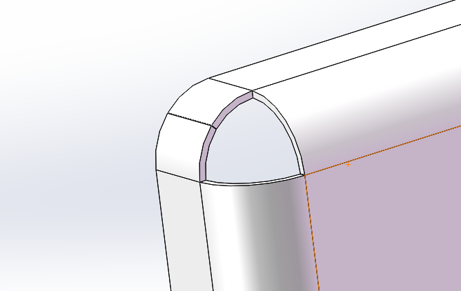
Click OK and use the same method to cut out gaps in the remaining rounded corners
Click on the entity to convert sheet metal
Select the blue surface for face 1, and select all arcs at the arrow for the bending edge line
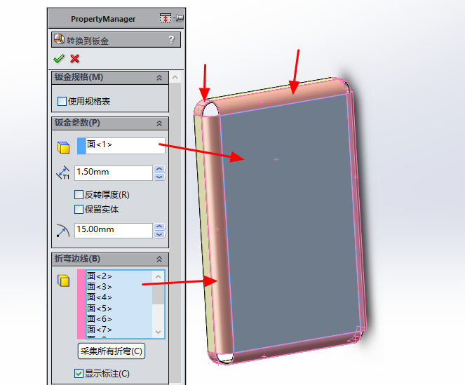
Set the bending coefficient K factor to 0.5
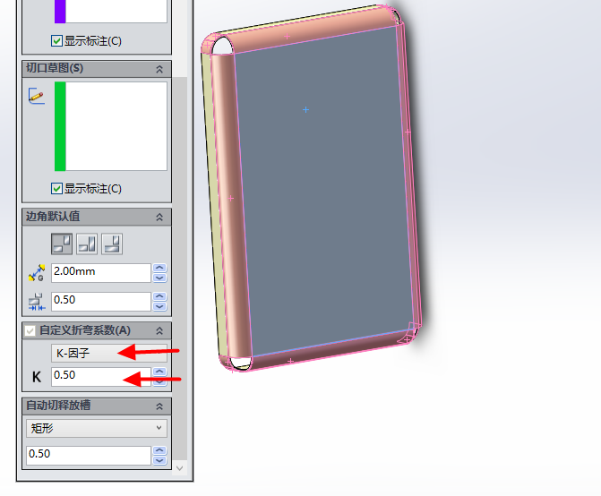
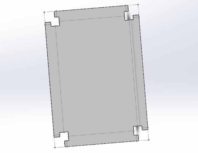
Click on the expand button in the following image
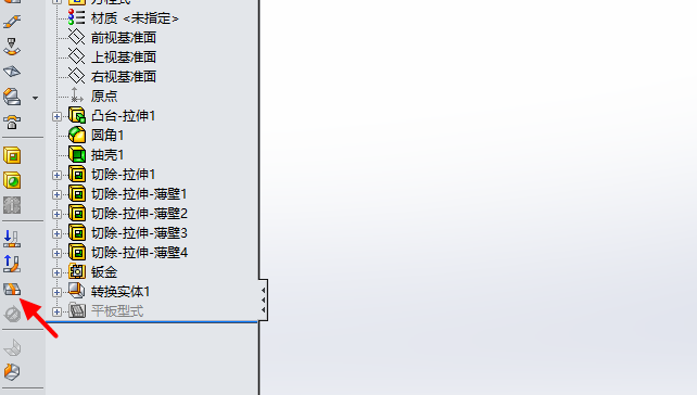
Generate expansion, right-click on the expanded surface to generate CAD format
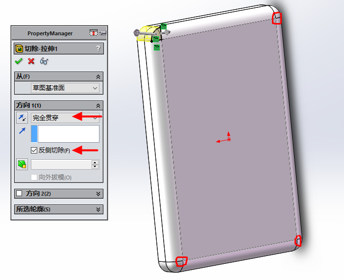
Returning to the solid parts of the shell, set the parameters for stretching and cutting, and pay attention to selecting the opposite side cutting
Generate as shown in the following figure
Draw a stretching and cutting sketch on the following surface
Click on stretch and cut to form to a vertex
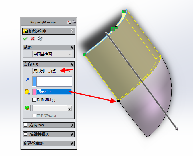
Click OK
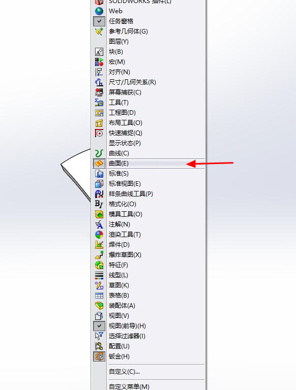
Right click on the top blank space
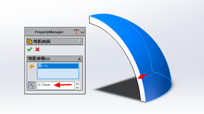
Click on the surface at the arrow to invoke the surface drawing command, and click on the equidistant surface at the arrow
Offset distance is half the thickness of the board, 0.75. Offset inward
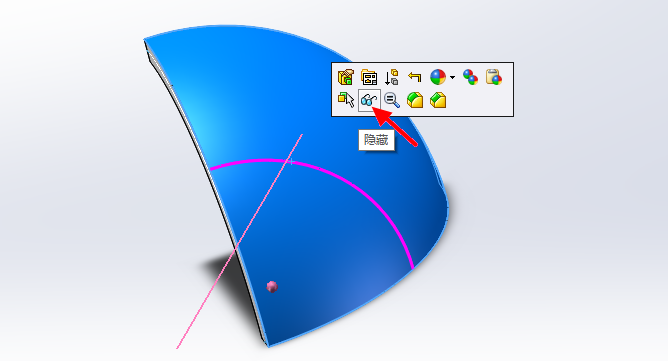
Click on the blue surface, click hide
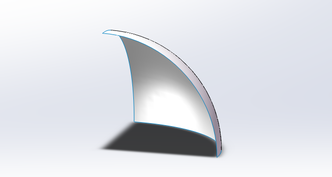
The following figure shows the offset surface
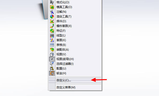
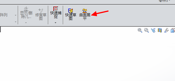
Right click on the blank space at the top and select 'Customize'
Select Command - Surface
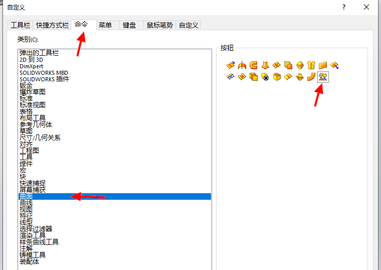
Press and hold the surface flattening command, drag to the top blank space
Click on the surface flattening button, select the face and vertex according to the arrow
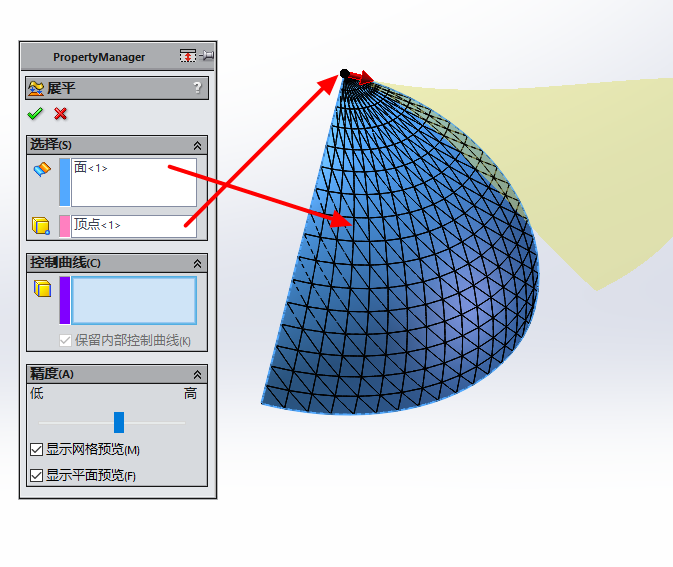
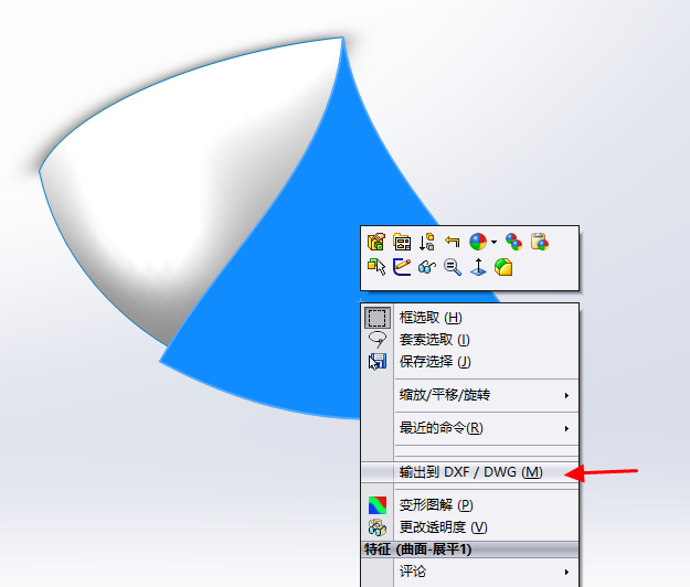
Unfold the surface. The blue surface in the following image represents the expansion of the rounded corners. Click to export to DXF/DWG to output the expansion
The above is the method for unfolding two sheet metal parts