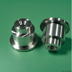
Process the sleeve part shown in Figure 1, with a blank diameter of 55mm, a length of 50mm, and a material of 45 steel: chamfer 145 not specified, and Ra12.5 for the rest.
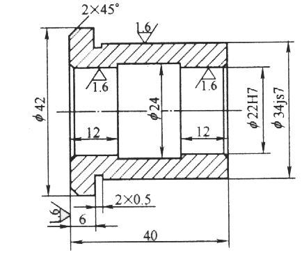
Figure 1 Sleeve components
Table 1: Procedure for Processing Outer Circles with Diameter of 34mm and 42mm and Cutting 20.5 Groove
program
explain
%7101
Program Name
N10 G92 X100 Z100
Set the workpiece coordinate system
N20 M03 S500
The spindle rotates forward at a speed of 500r/min
N30 M06 T0101
Replace the 0 # tool (coarse turning tool) with a replacement number of 01
N40 G90 G00 X50 Z2
Quickly locate the outer circle with a diameter of 50mm, 2mm away from the end face
N50 G80 X42.5 Z-40.5 F200
Coarse car with a diameter of 42mm and a radial allowance of 0.5mm
N60 G80 X34.5 Z-34 F200
Coarse car with a diameter of 34mm and a radial allowance of 0.5mm
N70 G01 X31 Z1 F200
Move the blade tip to a diameter of 31mm, 1mm away from the end face
N80 X35 Z-1
Chamfering 145
N90 X42
Move the blade tip to a diameter of 42mm
N100 Z-34
Move the blade tip to 34mm away from the end face
N110 Z-40.5
Precision car with a diameter of 42mm outer circle
N120 X45
Retract the blade to a diameter of 45mm
N130 G00 X100 Z100
Quickly locate the blade tip to a diameter of 100mm, 100mm away from the end face
N135 T0100
Clear the knife deviation
N140 M06 T0202
Replace the groove cutter with a width of 2mm
N150 G00 X45 Z-34
Quick positioning of the cutting edge with a diameter of 45mm and a distance of 34mm from the end face
N160 G01 X33 F50
Cut a slot of 20.5
N170 X48
Move the blade tip to a diameter of 48mm
N180 G00 Z-42.5
Move the blade tip to a distance of 42.5mm from the end face
N190 G01 X0 F50
Cut the workpiece and maintain a length of 40.5mm
N200 G00 X100 Z100
Quickly locate the blade tip to a diameter of 100mm, 100mm away from the end face
N210 T0200
Clear the knife deviation
N215 M05
Spindle stop
N220 M02
Program ends
Table 2: Procedure for Machining Inner Holes
program
explain
%7102
Program Name
N10 G92 X100 Z100
Set the workpiece coordinate system
N20 M03 S500
The spindle rotates forward at a speed of 500r/min
N30 M06 T0101
Replace the 01 tool (end face turning tool) with a replacement number of 01
N40 G90 G00 X44 Z0
Quickly locate at a diameter of 44mm
N50 G01 X20 F50
Car end face
N60 G00 Z50
Quickly locate the blade tip to a distance of 50mm from the end face
N70 X100
Quickly locate the blade tip to a diameter of 100mm
N75 T0100
Clear the knife deviation
N80 M06 T0202
Replace the knife with the 02 number (inner hole knife) and make up for it
N90 G00 X18 Z2
Quick positioning of blade tip
N100 G80 X21.6 Z-41 F200
Coarse car with a diameter of 22mm and a radial allowance of 0.4mm
N110 G01 X26 Z1 F50
N120 X22 Z-1
Chamfering 145
N130 Z-40.5
Fine tuned inner hole with a diameter of 22mm
N140 G01 X18
Retract the blade tip to a diameter of 18mm
N150 Z100
N160 X100
N165 T0100
Clear the knife deviation
N170 M06 T0303
Change the knife and use a 4mm inner hole slotting knife
N180 G00 X18 Z2
N190 Z-16.5
Quick positioning of blade tip
N200 G01 X23.5 F50
Cutting back blade groove
N210 X20
Retract the blade to a diameter of 20mm
N220 G81 X23.5 Z-20.5 F50
Cutting groove
N230 G81 X23.5 Z-24.5 F50
N240 G81 X23.5 Z-28 F50
N250 G01 Z-28
Blade tip movement positioning
N260 X24
Precision machining groove
N270 Z-16
N280 X20
Retract the blade to a diameter of 20mm
N290 G00 Z100
Quickly retract the blade tip to a distance of 100mm from the end face
N300 X100
Quickly retract the blade tip to a diameter of 100mm
N310 T0000
Clear the knife deviation
N315 M05
Spindle stop
N320 M02
Program ends
Table 3: Program for Precision Machining of a 34mm Outer Circle
program
Explanation:% 7103
Program Name
N10 G92 X100 Z100
Set the workpiece coordinate system
N20 M03 S1000
The spindle rotates forward at a speed of 1000r/min
N30 M06 T0101
External precision turning tool
N40 G00 Z2
N50 X36
N60 G01 X30 Z1 F50
N70 X34 Z-1
Chamfering 145
N80 Z-34
Fine tuned outer circle with a diameter of 34mm
N90 G01 X45
N100 G00 X100 Z100
Quickly locate the blade tip to a diameter of 100mm, 100mm away from the end face
N110 T0000
Clear the knife deviation
N115 M05
Spindle stop
N120 M02
Program ends
Clamp the outer circle with a diameter of 50mm and align it. Rough machining of outer circle with a diameter of 34mm, machining of outer circle with a diameter of 42mm, and cutting of groove with a diameter of 20.5. The knife used has an outer circle machining positive deviation knife (T01) and a cutting groove knife (T02) with a width of 2mm. The processing route is: rough machining of the outer circle with a diameter of 42mm (leaving a margin), rough machining of the outer circle with a diameter of 34mm (leaving a margin), precision machining of the outer circle with a diameter of 42mm, and cutting of the groove. The processing program is shown in Table 1. Use soft claws to clamp the outer circle with a diameter of 34mm and process the inner hole. The knife used has a 45 end face knife (T01), an inner hole turning tool (T02), and a slotting knife (T03) with a width of 4mm. The processing technology route is: rough machining of the end face with a diameter of 22mm, precision machining of the inner hole with a diameter of 22mm, and slotting of the inner hole with a diameter of 2416. The processing program is shown in Table 2. The workpiece is fitted with a spindle, clamped with two tips, and precision machined with a diameter of 34mm on the outer circle. The tool used is a precision machined positive offset tool (T01). The processing technology route is: precision machining of the outer circle with a diameter of 34mm. The processing program is shown in Table 3.


 Spanish
 Arabic
 French
 Portuguese
 Belarusian
 Japanese
 Russian
 Malay
Malay Icelandic
 Bulgarian
 Azerbaijani
 Estonian
 Irish
Irish Polish
 Persian
 Boolean
 Danish
 German
 Filipino
 Finnish
 Korean
 Dutch
Dutch Galician
 Catalan
 Czech
Czech Croatian
 Latin
Latin Latvian
 Romanian
 Maltese
 Macedonian
 Norwegian
 Swedish
 Serbian
 Slovak
 Slovenian
 Swahili
 Thai
Thai Turkish
 Welsh
Welsh Urdu
Urdu Ukrainian
 Greek
Greek Hungarian
 Italian
 Yiddish
 Indonesian
 Vietnamese
 Haitian Creole
 Spanish Basque

