Worm gear is a type of gear that meshes with a worm and has a special tooth profile. The cutting of worm gear teeth is generally completed by a hobbing machine, mainly using two methods: hobbing and flying cutting. Recently, a friend inquired about how to adjust the installation angle and the precautions to be taken when machining worm gears with rolling cutters. Today, let's talk about this topic.
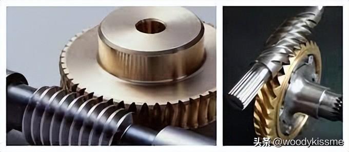
When manufacturing precision worm gears, gear hobbing, honing, or grinding can be performed after hobbing or gear cutting.
Hobbing gear 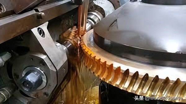
Using a worm gear rolling cutter with the same basic parameters as the working worm, the tooth profile is cut according to the principle of generating method. If the radial feed method is used for gear rolling, the rolling cutter and the workpiece roll in pairs according to a transmission ratio of Z 2/Z 1 (Z 1 is the number of threads on the working worm, Z 2 is the number of teeth on the worm wheel), gradually approaching each other until the center distance is equal to the center distance when the working worm and worm wheel mesh. When using the tangential feed method for gear hobbing, in addition to ensuring tool rotation, the machine tool also needs to have axial feed; at the same time, the worktable of the machine tool also needs to increase corresponding additional rotation to achieve generating motion, which requires the use of differential chains. Therefore, the machining accuracy of tangential feed method is generally not as good as radial feed method, but the tooth surface quality is better and there will be no root cutting phenomenon. The accuracy of rolling and cutting worm gears can generally reach level 6-8 (JB162-60). The hobbing of precision worm gears requires the use of high-precision rolling cutters on high-precision indexing worm gear hobbing machines. Mechanical or electronic transmission chain error correction devices can also be installed on general-purpose hobbing machines to improve machining accuracy, with a maximum machining accuracy of up to level 3.
Flying Knife Cutting Teeth 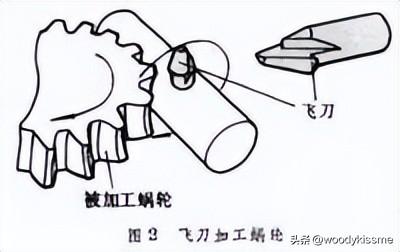
A flying knife is equivalent to one tooth of a worm gear rolling cutter. Flying knife cutting can only use tangential feed method. On the hobbing machine, the flying knife can rotate one revolution and the worm wheel can rotate Z 1 tooth. In addition, the tangential feed of the flying knife and the additional rotation of the worktable can also cut the correct tooth profile according to the principle of unfolding method, with an accuracy of 7-8 levels. Flying knives are easy to manufacture, but have low productivity in cutting teeth, making them suitable for use in single piece production and repair work.
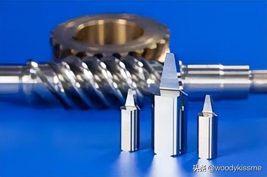
The basic parameters of the gear shaving cutter are the same as those of the working worm. Worm gear shaving is generally carried out using a hobbing machine, which can be driven by a shaving cutter to freely shave the worm gear teeth, or forcibly shave the teeth under the control of the machine tool transmission chain, resulting in improved tooth surface quality and accuracy after shaving.
After honing and grinding the worm gear teeth or cutting them with a flying knife, in order to improve the quality of the tooth surface and the contact between the worm gear and the worm gear during meshing, honing or grinding can be carried out on the hobbing machine. A honing tool is a honing worm made by casting a mixture of abrasive, plastic, and resin onto a substrate. During gear grinding, a grinding worm made of cast iron is used to grind the worm wheel with abrasive.
The above are different processing methods for worm gears. Today's topic is: how to install the worm gear rolling cutter when rolling and cutting worm gears, and what issues to pay attention to when rolling and cutting:
Roll cutting worm gear 1. Ordinary worm gear rolling cutter
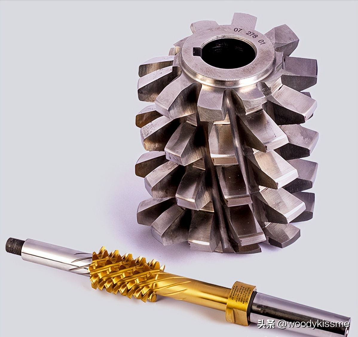
Usually, when processing worm gears, the basic worm gear of the standard worm gear rolling cutter (hereinafter referred to as the rolling cutter) used conforms to the working worm gear that meshes with the processed worm gear. Its main parameters, such as modulus, pressure angle, pitch circle diameter, number of heads, spiral direction, and spiral rise angle, are consistent with the meshing worm shaft. Moreover, when processing worm gears, the machining center distance of the rolling cutter is the same as the working center distance, so that the machined worm gear can theoretically ensure correct meshing with the worm gear.
When a regular rolling cutter rolls a worm gear, the rolling cutter is in the working position of the working worm gear, that is, the tool is in a horizontal state and meshes with the worm gear in a positive staggered space. It slowly cuts inward from the radial direction, and when it reaches the working center distance, the rolling teeth are completed and the worm gear rolling is finished.
2. Increased diameter worm gear rolling cutters (large outer diameter rolling cutters), but in actual production, it has been found that the worm gear meshing effect of traditional rolling cutters is often unsatisfactory, and the transmission torque is also difficult to meet the expected requirements. The development and use of increased diameter worm gear rolling cutters have solved this problem. Below is a brief introduction to the characteristics, basic design principles, and correct usage methods of the increased diameter worm gear rolling cutter.
The increased diameter worm gear rolling cutter adopts the local contact theory design, and the pitch circle diameter of the rolling cutter is slightly larger than the pitch circle of the working worm (non dual), so theoretically it is not a local contact, but a "point contact". However, during loading and use, due to elastic deformation, the point contact becomes a small local surface contact, and the contact surface is elliptical, thus meeting the requirement of concentrated meshing spots in the middle.
This point contact transmission overcomes the disadvantage of poor lubrication performance due to the instantaneous contact line of the line contact worm gear pair being close to the relative velocity direction, thereby improving the transmission efficiency of the wheel system; On the other hand, due to the reduced sensitivity of transmission quality to manufacturing and installation errors of worm gear pairs, the requirements for manufacturing and installation accuracy of worm gear pairs are lowered. It also allows the worm gear rolling cutter to have more regrinding times, effectively extending the service life of the rolling cutter. In some cases, the pitch circle of the worm gear is too small, which makes it difficult to manufacture the rolling cutter and has poor strength. Increasing the diameter can solve this problem and make rolling cutter manufacturing possible.
3. The design principle of the increased diameter worm gear rolling cutter is based on the meshing principle of helical gears, so that the normal base joint of the rolling cutter's basic worm is equal to that of the working worm. After increasing the diameter, the normal pressure angle at the basic worm pitch circle of the rolling cutter remains unchanged, the same as the working worm, the number of heads remains unchanged, and the normal modulus of the two is the same.
Generally, the percentage increase of the dividing circle is selected first, and the selection of the diameter increase is usually based on experiments and experience. Its size is related to the type of worm gear being processed and the size of the contact area. Generally, when the worm gear is single headed, the larger value is taken, and when it is multi headed, the smaller value is taken. Of course, it can also be calculated, but the calculation process is relatively complex.
The relationship between the increase in diameter and the contact area of 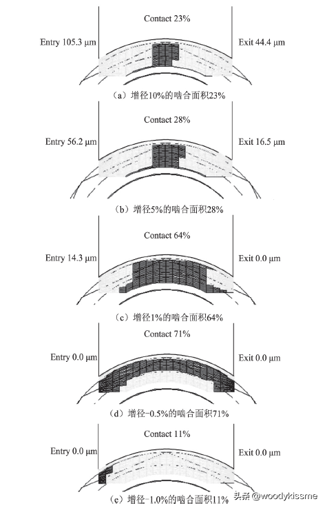
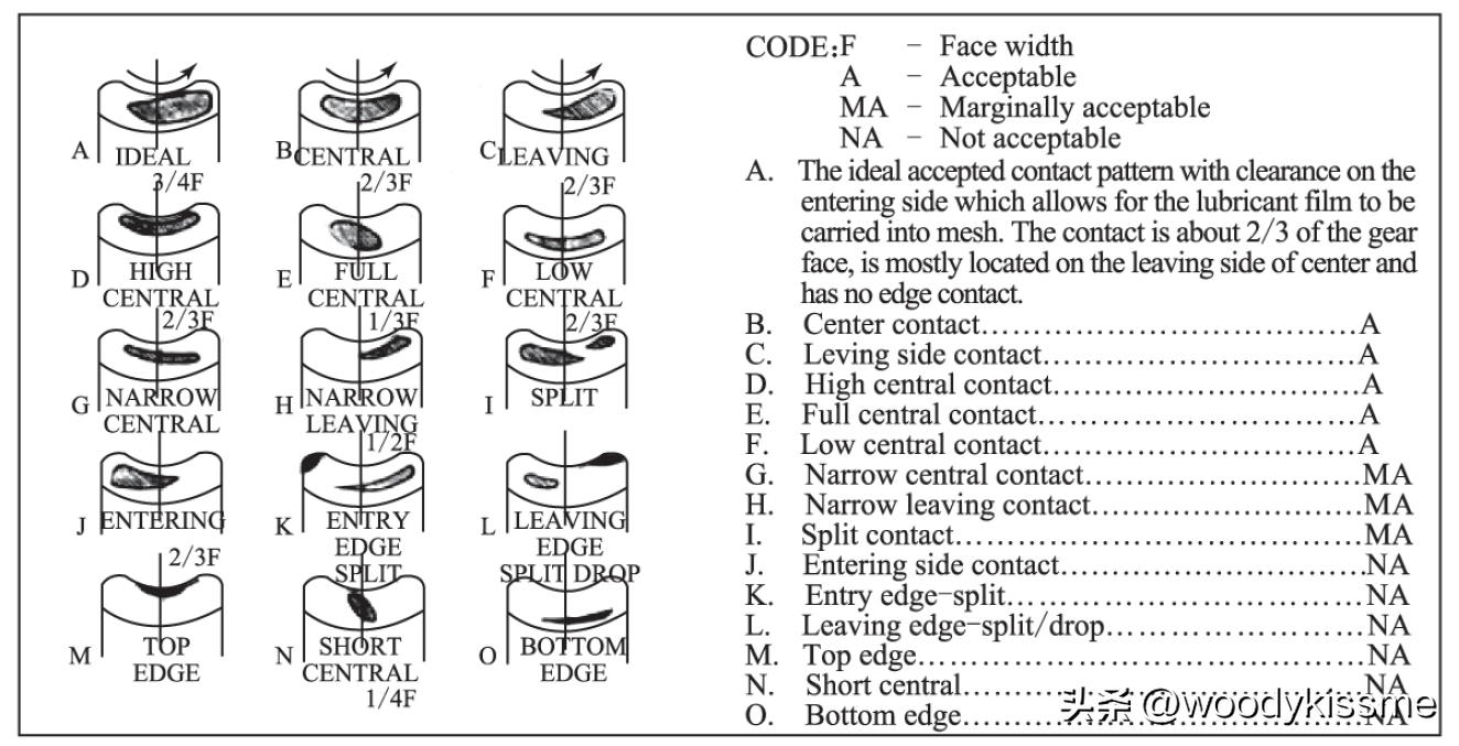
Generally speaking, the increase in diameter is relatively large, and based on experience, it is possible to achieve a 20% or even greater increase in diameter. Calculate the increase in diameter according to this requirement.
Given: worm gear mx, α x (α n), d (r), λ, n (where m is the modulus, α is the pressure angle, d is the pitch circle diameter, r is the radius, λ is the thread angle, and n is the number of heads), and worm gear width b2. Any subscript containing 'o' in the symbol indicates a cutting tool, while any subscript without 'o' indicates a working worm gear; The subscript x represents the axial direction, n represents the normal direction, and 2 represents the worm gear.
Spiral angle of worm: β=90- λ
If the increment of the pitch radius of the rolling cutter is Fr, and the pitch radius of the rolling cutter after increasing the diameter is ro, then:
ro=r+Fr
cosβo=rcos(β)/ro
mxo=mxsinβ/sinβo
The corresponding increment of center distance during gear hobbing is:
ΔA=Fr
Installation angle of gear hobbing: SA=β 0- β
After the rolling cutter is re ground with a shield, the installation angle needs to be recalculated due to the decrease in the outer diameter of the rolling cutter. Generally, the design of rolling cutters takes into account the issue of grinding. So in the design process, an additional value Δ r (grinding capacity, usually around 0.1M) will be added on top of the previous one. At this point:
ro'=ro+Δr
do'=2ro'
tanβo'=tan(βo)(ro+Δr)/ro
λo'=90-βo'
ΔA'=Fr+Δr
At this point, the installation angle should be: SA&# 39= β-βo'
4. According to the above design principles, the main difference between the increased diameter worm gear rolling cutter and the ordinary rolling cutter is that the modulus of the increased diameter rolling cutter is no longer equal to that of the original worm gear, but slightly smaller than that of the original worm gear; The thread angle is also different from the original value.
Structural differences between increased diameter worm gear cutters and traditional worm gear cutters

Differences in the use of increased diameter worm gear cutters and traditional worm gear cutters

5. Instructions for using the increased diameter worm gear rolling cutter: Due to the fact that the thread angle of the increased diameter worm gear rolling cutter is no longer equal to the thread angle of the working worm gear, the knife is no longer horizontal when machining the worm gear, but needs to be adjusted by a small installation angle (pay attention to the direction). The gear center distance is not equal to the assembly center distance, but slightly greater than the assembly center distance. After grinding, the diameter of the blade becomes smaller and the parameters change, resulting in changes in the above items during each rolling process. Therefore, when using an increased diameter rolling cutter to machine worm gears, it is necessary to detect the contact spots on the first worm gear. Based on the condition of the contact spots, the installation angle of the rolling cutter can be adjusted to ensure that the contact spots of the worm gear are in the middle of the worm gear before officially starting to process the worm gear, in order to achieve the expected effect.
In order to ensure that the helix angle of the worm gear processed by the increased diameter rolling cutter meets the requirements of the drawing, the rolling cutter holder must be rotated by an angle when installing the increased diameter rolling cutter. As for how these process parameters change, generally tool suppliers will provide a parameter adjustment table.
Attention: (1) After grinding the tool, it is necessary to re measure the outer diameter value of the rolling cutter.
(2) Ensure correct installation angle and center distance.
(3) Observe the meshing spots and adjust the installation angle in a timely manner.
If this article has been helpful to you, please give it a like. Thank you!
I am Woodykissme, and I regularly share content related to mechanical transmission and gear processing. If you are interested in this area, please follow me. I hope to discuss with everyone:
The design and processing methods of gears, as well as related issues regarding the design, manufacturing, and use of cutting tools used for gear processing.
Design and calculation methods for gear cutting tools, development of related application programs, CAD secondary development and automatic drawing related technical issues. In terms of tool application, the cutting parameters, coatings, and service life of the tool, as well as the problems encountered during machining and their solutions.


 Spanish
 Arabic
 French
 Portuguese
 Belarusian
 Japanese
 Russian
 Malay
Malay Icelandic
 Bulgarian
 Azerbaijani
 Estonian
 Irish
Irish Polish
 Persian
 Boolean
 Danish
 German
 Filipino
 Finnish
 Korean
 Dutch
Dutch Galician
 Catalan
 Czech
Czech Croatian
 Latin
Latin Latvian
 Romanian
 Maltese
 Macedonian
 Norwegian
 Swedish
 Serbian
 Slovak
 Slovenian
 Swahili
 Thai
Thai Turkish
 Welsh
Welsh Urdu
Urdu Ukrainian
 Greek
Greek Hungarian
 Italian
 Yiddish
 Indonesian
 Vietnamese
 Haitian Creole
 Spanish Basque

