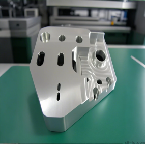
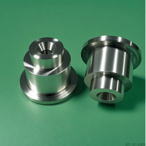
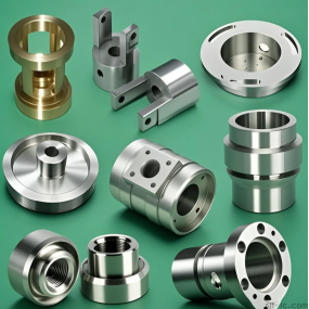
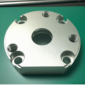
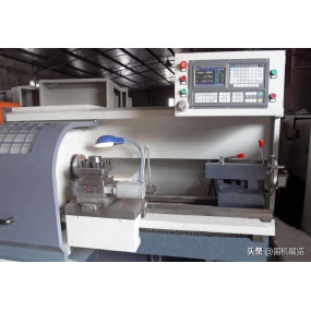
Numerical control lathe is a high-precision and high-efficiency automated machine tool. The use of numerical control lathe can improve processing efficiency and create more value. The emergence of numerical control lathe has enabled enterprises to get rid of outdated processing technology. The processing technology of numerical control lathe is similar to that of ordinary lathe. However, since numerical control lathe is a one-time clamping and continuous automatic processing to complete all turning processes, the following aspects should be noted.
Reasonably choose cutting parameters
For efficient metal cutting, the material being machined, cutting tools, and cutting conditions are the three major elements. These determine the processing time, tool life, and processing quality. The economically effective processing method must be a reasonable choice of cutting conditions.
The three elements of cutting conditions: cutting speed, feed rate, and cutting depth directly cause tool damage. With the increase of cutting speed, the temperature of the cutting edge will rise, resulting in mechanical, chemical, and thermal wear. Increasing cutting speed by 20% will reduce tool life by half.
The relationship between feed conditions and tool wear occurs within a very small range. But with a large feed rate, the cutting temperature rises, and there is significant wear later on. It has less impact on the cutting tool than the cutting speed. Although the impact of cutting depth on cutting tools is not as significant as cutting speed and feed rate, in micro depth cutting, the material being cut produces a hardened layer, which also affects the tool's lifespan.
Users need to choose the cutting speed based on the material being processed, hardness, cutting state, material type, feed rate, cutting depth, etc.
The selection of the most suitable processing conditions is based on these factors. Regular and stable wear and tear to achieve lifespan is the ideal condition.
However, in practical operations, the choice of tool life is related to tool wear, changes in machined dimensions, surface quality, cutting noise, machining heat, and other factors. When determining the processing conditions, it is necessary to conduct research based on the actual situation. For difficult to machine materials such as stainless steel and heat-resistant alloys, coolants or blades with good rigidity can be used.
How to determine the three elements of cutting processing
How to correctly select these three elements is a major content of the course on metal cutting principles, and the basic principles for selecting these three elements are:
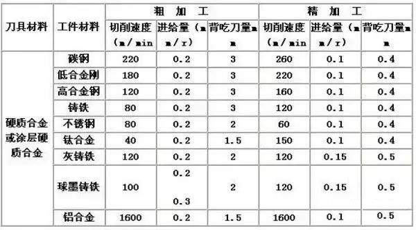
(1) Cutting speed (line speed, circumferential speed) V (m/min)
To select the spindle revolutions per minute, it is necessary to first know how much cutting line speed V should be taken. The choice of V depends on the tool material, workpiece material, processing conditions, etc.
Tool material:
Hard alloy, V can achieve a high value, generally above 100 meters per minute, and technical parameters are usually provided when purchasing blades:
How many line speeds can be selected when processing what materials. High speed steel: V can only be obtained at a relatively low level, generally not exceeding 70 meters per minute, and in most cases below 20-30 meters per minute.
Workpiece material:
High hardness, low V value; Cast iron, with a low V value, can be used for cutting tools made of hard alloy at a speed of 70-80 meters per minute; Low carbon steel can have a V value of over 100 meters per minute, while non-ferrous metals can have a higher V value (100-200 meters per minute). Quenched steel and stainless steel should have a lower V value.
Processing conditions:
Rough machining, take a lower V value; Precision machining, with a higher V value. The rigidity system of machine tools, workpieces, and cutting tools is poor, and V is taken as low. If the CNC program uses S as the spindle speed per minute, then S (spindle speed per minute) should be calculated based on the workpiece diameter and cutting line speed V, where S=V (cutting line speed) * 1000/(3.1416 * workpiece diameter). If the CNC program uses a constant line speed, S can directly use the cutting line speed V (meters/minute)
(2) Feed rate (feed rate)
F mainly depends on the surface roughness requirements of the workpiece processing. When precision machining, the surface requirements are high, and the cutting amount should be small: 0.06~0.12mm/spindle per revolution. When rough machining, it can be larger. It mainly depends on the strength of the tool, which can generally be above 0.3. When the main rake angle of the tool is large, the strength of the tool is poor, and the feed rate cannot be too large. In addition, the power of the machine tool and the rigidity of the workpiece and cutting tool should also be considered. The CNC program uses two units of feed rate: mm/min and mm/spindle per revolution. The units used above are all mm/spindle per revolution. If mm/min is used, the formula can be used to convert it: feed rate per minute=feed rate per revolution * spindle revolutions per minute
(3) Cutting depth (cutting depth)
When precision machining, it is generally advisable to take a radius value of 0.5 or less. During rough machining, it is determined based on the condition of the workpiece, tool, and machine tool. Generally, small lathes (with a maximum machining diameter of 400mm or less) are used to turn 45 # steel in a normalized state, and the depth of the radial cutting tool is generally not more than 5mm. Additionally, it should be noted that if the spindle speed of the lathe adopts ordinary variable frequency speed regulation, when the spindle speed is very low per minute (below 100-200 revolutions per minute), the motor output power will significantly decrease, and the cutting depth and feed rate can only be achieved very little at this time.
Reasonable selection of cutting tools
When rough turning, it is necessary to choose cutting tools with high strength and good durability to meet the requirements of large back cutting and large feed rate during rough turning.
When precision machining, it is necessary to choose tools with high precision and good durability to ensure the required machining accuracy.
To reduce tool changing time and facilitate tool alignment, machine clamped knives and machine clamped blades should be used as much as possible.
Reasonably choose fixtures
1. Try to use universal fixtures to clamp workpieces and avoid using specialized fixtures;
2. Align the positioning benchmarks of the parts to reduce positioning errors.
Determine the processing route
The machining route refers to the motion trajectory and direction of the tool relative to the part during the CNC Machining process.
1. It should be able to ensure the machining accuracy and surface roughness requirements;
2. The processing route should be shortened as much as possible to reduce the tool idle time.
The relationship between processing route and machining allowance
At present, in the absence of widespread use of CNC lathes, excessive allowance on the blank, especially the allowance containing forged or cast hard skin layers, should generally be arranged for processing on ordinary lathes. If it is necessary to use a CNC lathe for machining, attention should be paid to the flexible arrangement of the program.
Key points for fixture installation
At present, the connection between the hydraulic chuck and the hydraulic clamping cylinder is achieved by a pull rod. The key points of hydraulic chuck clamping are as follows: first, use a handle to remove the nut on the hydraulic cylinder, remove the pull tube, and extract it from the rear end of the spindle. Then, use a handle to remove the chuck fixing screw to remove the chuck.


 Spanish
 Arabic
 French
 Portuguese
 Belarusian
 Japanese
 Russian
 Malay
Malay Icelandic
 Bulgarian
 Azerbaijani
 Estonian
 Irish
Irish Polish
 Persian
 Boolean
 Danish
 German
 Filipino
 Finnish
 Korean
 Dutch
Dutch Galician
 Catalan
 Czech
Czech Croatian
 Latin
Latin Latvian
 Romanian
 Maltese
 Macedonian
 Norwegian
 Swedish
 Serbian
 Slovak
 Slovenian
 Swahili
 Thai
Thai Turkish
 Welsh
Welsh Urdu
Urdu Ukrainian
 Greek
Greek Hungarian
 Italian
 Yiddish
 Indonesian
 Vietnamese
 Haitian Creole
 Spanish Basque

