The method is as simple as that, but the value is enormous. The key is whether you value it or not!
This is just one of the methods, there are many more methods that Jun Ge will teach you later.
Drawing a tool path diagram is a reverse engineering method, and the type of tool path will determine how to write the program later.
For example, the serrated thread cutting path diagram is shown below, with different tooth angles on both sides.
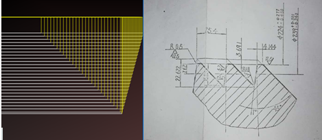
For example, the tool path diagram for TR thread below, with borrowed tools on both sides
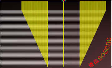
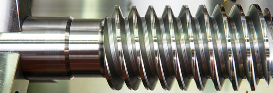
Today's article will talk about macro programming for T-shaped threads
As shown in the above knife path diagram: Layered vehicle, three knives per layer, that is, the middle first, and then the left and right borrowed knives on both sides
Enlarge the knife path diagram as shown in the following figure:
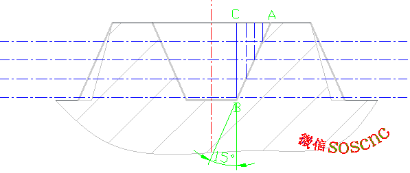
In this way, everyone can intuitively see that as the cutting depth deepens, the tool needs to move along the AB line, so that the borrowed tool comes out with the required thread profile.
In other words, there is a relationship between the depth of the knife X and the size in the Z direction, which satisfies the Pythagorean law, that is, TAN15=AC/BC
So we can deduce: AC=TAN15 * BC
This relationship is too important. In the subsequent programming, as the cutting depth BC changes, AC also changes according to this relationship, thus processing the Tr type thread profile shape.
So the contour shape of Tr does not necessarily mean that Tr threads can be processed satisfactorily.
Because cutting tools also need to be considered during processing.
Because each Tr type thread has a specific tooth size.
For example, the selected blade width is 2mm (for left and right borrowed blades, the blade width needs to be smaller than the tooth base width)
For example, TR100 * 12 external thread, the relevant dimensions are as follows:
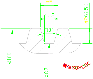
I can set any number of variables as shown in the above figure
#2 represents tooth height, which is the depth of the incision
#5 represents the total width of the teeth, which is the size of the thread profile we need to process
#5= 4.12+2*TAN[15]*#2
Because cutting tools also have a width, the actual width of the alveolar cavity should be:
Tooth base width+2 x slope width - tool width.
So the final # 5=4.12+2 * TAN [15] * # 2-2 (including the tool width)
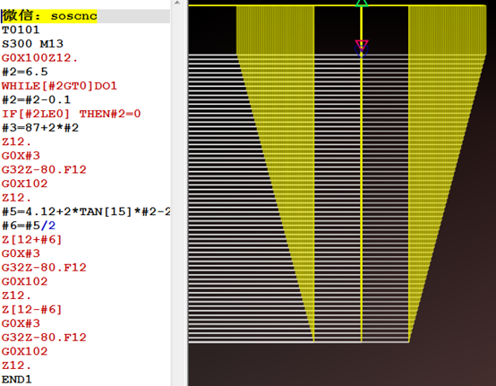
Okay, that's all for the analysis. Just go straight to the program
T0101
S300 M13
G0X100Z12. (Quickly move to the starting point of the thread)
#2=6.5 (initial assignment of tooth height)
WHILE [# 2GT0] DO1 (If the tooth height has not reached 0, it means that the thread base diameter size has not been reached yet)
#2=# 2-0.1 (cutting amount, 0.1 per layer of vehicle, one-sided value)
IF[#2LE0] THEN#2=0
#3=87+2 * # 2 (Since # 3 is assigned a value of 6.5 and the first cut is made at the larger diameter of the thread, the smaller diameter plus the height of both teeth equals the larger diameter. When the value of # 2 changes, it means that the larger diameter also changes, thus achieving layered cutting)
Z12. (Z12 is the positioning reference, and the starting points of the left and right borrowed knives in the subsequent program are all based on Z12)
G0X # 3 (downward cutting in X direction)
G32Z-80.F12 (thread cutting)
G0X102 (retraction)
Z12. (Return blade)
#5=4.12+2 * TAN [15] * # 2-2 (The tooth width corresponding to the current tooth height is the basis for borrowing knives on both sides later)
#6=# 5/2 (since both sides borrow the knife, divide # 5 by 2 and divide equally)
Z [12+# 6] (First borrow a knife from the right side, add # 6 because the knife needs to move to the right)
G0X#3
G32Z-80.F12
G0X102
Z12.
Z [12- # 6] (First borrow a knife from the left, subtract # 6 as the tool needs to move to the left)
G0X#3
G32Z-80.F12
G0X102
Z12.
END1
G0X200.
Z200.
M30


 Spanish
 Arabic
 French
 Portuguese
 Belarusian
 Japanese
 Russian
 Malay
Malay Icelandic
 Bulgarian
 Azerbaijani
 Estonian
 Irish
Irish Polish
 Persian
 Boolean
 Danish
 German
 Filipino
 Finnish
 Korean
 Dutch
Dutch Galician
 Catalan
 Czech
Czech Croatian
 Latin
Latin Latvian
 Romanian
 Maltese
 Macedonian
 Norwegian
 Swedish
 Serbian
 Slovak
 Slovenian
 Swahili
 Thai
Thai Turkish
 Welsh
Welsh Urdu
Urdu Ukrainian
 Greek
Greek Hungarian
 Italian
 Yiddish
 Indonesian
 Vietnamese
 Haitian Creole
 Spanish Basque

