Regarding the issue of dimension annotation, many new technical personnel in the industry hold a drawing and want to annotate dimensions, but do not know how to start and how to express them perfectly. Each engineer's style of annotating drawings is different, but is there a popular method or a method suitable for beginners?
Generally speaking, drawings are not perfect, and anyone who creates any form of drawing can always pick out various flaws. Even if you think there are no problems with a drawing, during the leader's review, you are not asked to modify some harmless issues or if you think it is correct but have to modify it according to the leader's instructions.
For drawings, generally speaking, the more information there is, the more redundancy there is, and to a certain extent, it can also affect information exchange.
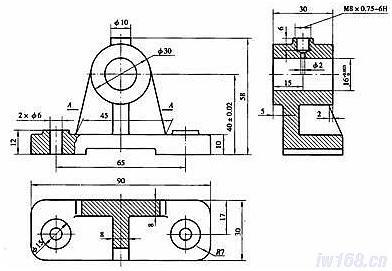
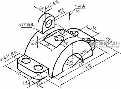
In order to annotate dimensions reasonably, it is necessary to understand the function of the parts, their assembly position in the machine, and the processing methods used, so as to select appropriate dimensional benchmarks and annotate dimensions reasonably.
Once you understand this rule, even the most complex product part dimension labeling will not be at a loss
Classify and explain various complex mechanical component drawings, how to label dimensions reasonably
Principle of reasonable dimensioning: 1. Important dimensions should be directly indicated
2. Avoid labeling as a closed dimensional chain
3. Consideration should be given to the convenience of measurement
4. Should comply with the processing sequence
5. Consider processing methods
6. Dimensional annotation method for common holes on parts
Common knowledge of mechanical drawing: dimensioning of part drawings, selection of benchmarks, and principles of reasonable annotation
The basic points to note for other drawings are: 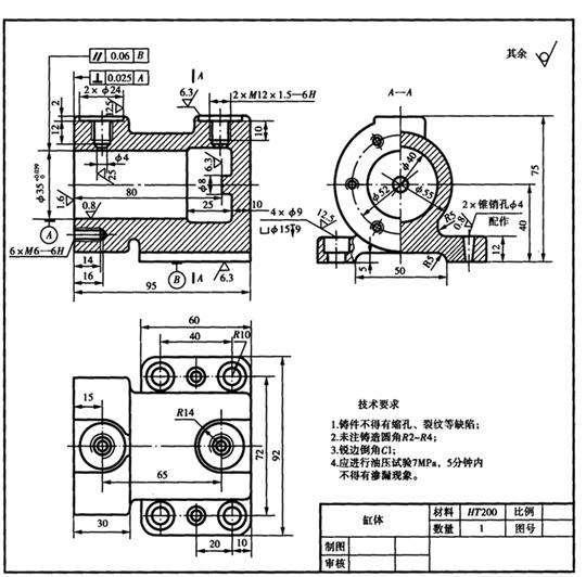
1. Fill in all possible fields in the frame, including name, number, scale, material, unit, weight, surface treatment, signature, etc.
2. Mark the dimensions and tolerances one by one, while highlighting the key points (3F dimensions, quality control points). Tolerance needs to be studied in conjunction with the company's production process capabilities, and cannot be marked for the sake of tolerance.
3. Communicate with the users of the drawings (processors, quality controllers, bosses, etc.) to discuss and approve some of their important feedback, which can be written on the drawings.
4. Well done. The view should generally be as large as possible; Use multiple colors, such as using one color for dimension marking and another color for positional tolerance marking; Sometimes using dimension chains for annotation can reduce the clutter of drawings.
5. Try to start making engineering drawings from 3D models, and include individual views that can better showcase the overall style of the components in the drawings.
Resolve the issue of increased annotation size in CAD local enlargement icons
Definition, annotation, and interpretation of various positional tolerances - truly comprehensive
Introduction to Calculation and Application of Size Chain: When designing and annotating dimensions in products, it is necessary to consider
The difference between three annotation methods: 10 (-0.2,+0.2) 9.8 (0,+0.4) 10.2 (0, -0.4)
Detailed explanation: Gap, transition, interference fit, base hole system, base axis system, fitting code and annotation examples
Mechanical drawing: Which of the four identical hole markings 4-10 and 410 is correct?
Don't say you can't understand the drawings anymore! Non technical personnel related to machinery should take a good look at the most basic drawing annotations
Mechanical Drawing: Detailed Explanation of the Concept and Annotation Method of Surface Roughness


 Spanish
 Arabic
 French
 Portuguese
 Belarusian
 Japanese
 Russian
 Malay
Malay Icelandic
 Bulgarian
 Azerbaijani
 Estonian
 Irish
Irish Polish
 Persian
 Boolean
 Danish
 German
 Filipino
 Finnish
 Korean
 Dutch
Dutch Galician
 Catalan
 Czech
Czech Croatian
 Latin
Latin Latvian
 Romanian
 Maltese
 Macedonian
 Norwegian
 Swedish
 Serbian
 Slovak
 Slovenian
 Swahili
 Thai
Thai Turkish
 Welsh
Welsh Urdu
Urdu Ukrainian
 Greek
Greek Hungarian
 Italian
 Yiddish
 Indonesian
 Vietnamese
 Haitian Creole
 Spanish Basque

