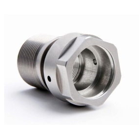
Brief introduction and industry overview of sheet metal:
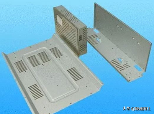
With the development of the automotive, communication, IT, and daily hardware manufacturing industries, sheet metal processing has become increasingly popular, and understanding sheet metal processing has become more necessary.
2. The operation of manually or mechanically making metal sheets, profiles, and pipes into parts with a certain shape, size, and accuracy is called sheet metal processing; It is widely used in the production of ventilation, air conditioning ducts and their components.
3. Sheet metal parts are mostly made of metal sheets and pipe fittings. Due to their light weight, high strength and stiffness, shape can be arbitrarily complex, low material consumption, no need for mechanical processing, and smooth surface, they are widely used in daily life and industrial production, such as barrels, basins, ventilation ducts, material conveying pipelines, automotive cover processing, etc. In addition, they can also be applied to external repair work of automobiles.
4. Metal sheet processing usually refers to methods such as shearing, bending, rolling, and flipping forming. Generally speaking, the process of using molds to complete various deformation processes is called sheet Metal Stamping, while the process of manually or mechanically forming sheet metal is called sheet metal processing.
Sheet metal material:
1. Electrolytic plates: SECC (N) (fingerprint resistant plate), SECC (P), DX1, DX2, SECD (stretch plate). Material hardness: HRB50+-5, tensile plate: HRB32~37
2. Cold rolled plates: SPCC, SPCD (stretch plate), 08F, 20, 25, Q235-A, CRS. Material hardness: HRB50+-5, tensile plate: HRB32~37.
3. Aluminum plate; AL, AL (1035), AL (6063), AL (5052), etc.
4. Stainless steel plates: SUS, SUS301 (302303304), 2Cr13, 1Cr18Ni9Ti, etc.
5. Other commonly used materials include: pure copper plates (T1, T2), hot-rolled plates, spring steel plates, aluminum zinc plated plates, aluminum profiles, etc.
Sheet metal processing technology:
The sheet metal processing technology can be basically divided into: marking, cutting, folding, rolling (bending), bending, biting or welding, flange making, and flange installation processes. This section mainly introduces processes such as marking, rolling, folding, biting, and bending.
(1) Draw a line
1. Most sheet metal parts are made of flat metal plates, so it is necessary to draw the actual surface dimensions of the sheet metal parts into a flat shape on the metal plate, which is called unfolding drawing.
2. According to the unfolding properties of the surface of the constituent parts, there are two types: expandable surfaces and non expandable surfaces.
3. The surface of the component can be completely flat on a flat surface without tearing or wrinkling, and this type of surface is called a deployable surface. Planes, cylinders, and cones belong to deployable surfaces. If the surface of a part cannot be naturally flattened and spread out on a flat surface, it is called an undetectable surface, such as the surface of a sphere, a circular ring, and a helical surface, which can only be approximately unfolded.
(2) Sheet metal processing method
1. Cutting: Cutting is the process of cutting materials into the desired shape according to unfolding. There are many methods for cutting materials, which can be divided into cutting, punching, and laser cutting according to the type and working principle of the machine tool.
1.1 Cutting - Use a cutting machine to cut the desired shape. The accuracy can reach 0.2mm or above, mainly used for cutting strips or cutting clean materials.
1.2 Punching and cutting - Use a CNC punching machine (NC) or a regular punching machine for cutting. Both cutting methods can achieve an accuracy of over 0.1mm, but the former has cutting marks and relatively low efficiency during cutting, while the latter has high efficiency but high single cost, making it suitable for large-scale production.
1.2.1 CNC punching machines use upper and lower molds to fix the material during cutting, and the worktable to move to punch and cut the sheet metal, producing the desired shape of the workpiece. There are mainly two types of CNC punching machines: Tailifu and AMADA.
1.2.2 A regular punch press uses the movement of upper and lower molds to punch out the required shape of the material using a dropping die. Ordinary punching machines generally need to be matched with a shearing machine to punch out the required shape, that is, after cutting the strip material with the shearing machine, the punching machine can punch out the required material shape.
1.3 Laser cutting - using laser cutting equipment to continuously cut the sheet metal to obtain the desired shape of the material. Its characteristic is high precision and the ability to process parts with very complex shapes, but the processing cost is relatively high.
2. Forming:
Sheet metal forming is a major processing method in sheet metal processing. Forming can be divided into two types: manual forming and machine forming. Hand forming is often used as a supplementary processing or finishing work and is rarely employed. However, when processing some materials with complex shapes or prone to deformation, manual forming is still indispensable. Hand forming is accomplished using simple fixtures and jigs. The following methods are mainly used: bending, edging, trimming, arching, curling, and shaping.
We mainly discuss machine forming here: bending forming, stamping forming.
2.1 Bending Forming - Fix the upper and lower molds separately on the upper and lower workbenches of the folding bed, use servo motors to transmit and drive the relative motion of the workbenches, and combine the shapes of the upper and lower molds to achieve bending forming of the sheet metal. The forming accuracy of bending can reach 0.1mm.
2.2 Stamping Forming - Using the power generated by the motor driven flywheel to drive the upper mold, combined with the relative shape of the upper and lower molds, the sheet metal is deformed to achieve the processing and forming of the parts. The precision of stamping forming can reach over 0.1mm. Punching machines can be divided into ordinary punching machines and high-speed punching machines.
3. Connection of metal sheets
Ventilation ducts and components made of metal sheets can be connected using methods such as bite joint connection, rivet connection, welding, etc. This section mainly introduces bite connections.
Fold and bite the edges of two pieces of sheet metal (or both sides of a piece of material) together and press them tightly against each other. This connection method is called biting (seam). Sheet metal connection is the process of connecting different parts together in a certain way to obtain the desired product. Sheet metal connections can be divided into welding, riveting, threaded connections, etc.
(1) Bite connection
1. Types of bites
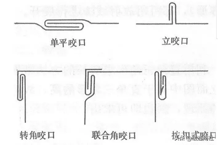
Corner bite and buckle style
2. Application of Bite
Various types of bites are mainly used in the following areas:
(1) Single flat bite is used for splicing seams of boards, longitudinal closure seams of ducts or components.
(2) Single bite is used for circular bends, back and forth bends, and horizontal seams of air ducts.
(3) Corner biting, joint corner biting, and snap on biting are used for longitudinal closure joints and rectangular elbows of rectangular ducts or components, as well as corner joints of tees.
(2) Bite width and allowance
The width of the bite depends on the thickness of the pipe fittings, as shown in Table 8-1.
The size of bite allowance is related to bite width, overlapping layers, and the machinery used.
2. For single flat bite, single vertical bite, and corner bite, the amount left on one board is equal to the bite width, while the amount left on the other board is twice the bite width. Therefore, the bite retention is equal to three times the bite width.
3. For joint corner bite, leave an amount equal to the bite width on one board and three times the bite width on the other board, resulting in a total retention of four times the bite width.
4. The bite allowance should be left on both sides of the board as needed.
Bites can be done manually or mechanically.
1. Manual biting
The manual biting process is as follows:
(1) The processing of a single flat bite (as shown in the figure below) involves placing a plate with pre drawn seam bending lines on the channel steel, aligning the seam bending lines with the edges of the channel steel
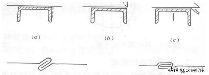
(1) Bite machines include linear bite machines and elbow bite machines, which can complete the bite forming of square, rectangular, circular pipes, elbows, tees, and variable diameter pipes. The bite shape is accurate, the surface is flat, the size is consistent, and the productivity is high. They are widely used in the processing of air conditioning and ventilation ducts.
(2) The process of bite forming mechanical bite is to pass the sheet metal through multiple pairs of rotating rollers with different groove shapes, gradually changing the curvature of the sheet edge from small to large, and gradually forming it.
(3) When making circular air ducts from sheet metal, it is necessary to roll and bend the sheet metal. When making rectangular ducts, it is necessary to fold the sheet metal square.
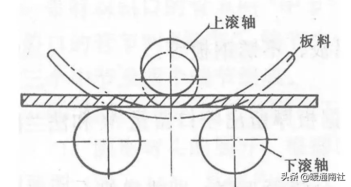
The method of bending the sheet metal through a rotating roller is called rolling, also known as rounding.
1. Basic principle: The basic principle of rolling and bending is shown in the figure. The sheet metal is placed on the lower roller, and the distance between the upper and lower rollers can be adjusted. When the distance is less than the thickness of the sheet metal, the sheet metal will bend, which is called compression bending. If continuously rolled, the sheet metal forms a smooth curvature within the range it is rolled to (but the two ends of the sheet metal are still straight due to the inability to roll, and must be eliminated when forming the part). So the essence of rolling is continuous bending.
3.1 Welding can be divided into: CO2 welding, Ar welding, resistance welding, etc
3.1.1 CO2 welding processing principle: Use protective gas (CO2) to mechanically isolate air and molten metal, preventing oxidation and nitriding of molten metal. It is mainly used for welding iron materials. Characteristics: firm connection and good sealing performance. Disadvantages: easy deformation during welding CO2 welding equipment is mainly divided into robot CO2 welding machines and manual CO2 welding machines.
3.1.2 Ar arc welding is mainly used for welding aluminum and stainless steel materials. Its processing principle and advantages and disadvantages are the same as CO2, and the equipment is also divided into robot welding and manual welding.
3.1.3 Working principle of resistance welding: Using the resistance heat generated by the current passing through the welding piece, the welding piece is melted and heated to connect the welding pieces The equipment mainly includes the Songxing series, Qilong series, etc.
3.2 Riveting can be divided into: pressure riveting connection and rivet connection, etc. Common riveting equipment includes riveting machines, riveting guns, and POP riveting guns.
3.2.1 Riveting connection is the process of pressing screws and nuts into the workpiece so that they can be connected to other parts through threads.
3.2.2 Rivet connection is the use of rivets to pull and rivet two components together.
Surface treatment:
The decorative and protective effects of surface treatment on product surfaces are recognized by many industries. In the sheet metal industry, surface treatment methods commonly used include electroplating, spraying, and other surface treatment methods.
1. Electroplating is divided into: galvanizing (color zinc, white zinc, blue zinc, black zinc), nickel plating, chrome plating, etc;
The main function is to form a protective layer on the surface of the material, which plays a protective and decorative role;
2. Spray painting is divided into two types: spray painting and powder spraying. After pre-treatment of the material, the coating is sprayed onto the surface of the workpiece with a spray gun and gas, forming a coating on the surface of the workpiece. After drying, it plays a protective role;
Handmade bend pipe
In non bending equipment or single piece small batch production, the number of bends is small, making it uneconomical to make bending molds. In this case, manual bending is used. The main processes of manual bending include sand filling, marking, heating, and bending.
(1) When manually bending pipes with sand filling, the following main methods are used to prevent deformation of the steel pipe section: filling the pipe with fillers (such as quartz sand, rosin, and low melting point alloys). For larger diameter steel pipes, sand is generally used. Before sand filling, plug one end of the steel pipe with a conical wooden stopper. There is an air outlet hole on the wooden stopper to allow the air inside the pipe to freely release when heated and expanded. After sand filling, also plug the other end of the pipe with a wooden stopper. The sand loaded into the steel pipe should be clean, dry, and tight.
For steel pipes with larger diameters, when it is inconvenient to use wooden plugs, steel plug plates can be used.
(2) Draw a line to determine the heating length of the steel pipe
(3) Heating can be done using charcoal, coke, coal gas, or heavy oil as fuel. Heating should be slow and uniform, and the heating temperature for ordinary carbon steel is generally around 1050 ℃. Cold bending is used for stainless steel and alloy steel pipes.
(4) The bent and heated steel pipe can be bent on a manual bending device.
Core bend pipe
Core bent pipe is a type of pipe that is bent back along the mold using a core shaft on a pipe bending machine. The function of the core shaft is to prevent deformation of the cross-section when the pipe is bent. The forms of core shafts include round head, pointed head, spoon shaped, one-way joint, universal joint, and flexible shaft.
The quality of a core bent pipe depends on the shape, size, and position of the core shaft extending into the pipe.
Coreless bend pipe
Coreless bending pipe is a method of controlling the deformation of the steel pipe section using the reverse deformation method on a bending machine. It causes a certain amount of reverse deformation to be applied to the steel pipe before entering the bending deformation zone, so that the outer side of the steel pipe protrudes outward to offset or reduce the deformation of the steel pipe section during bending, thereby ensuring the quality of the bent pipe.
Coreless bent pipes are widely used. When the bending radius of the steel pipe is greater than 1.5 times the diameter of the pipe, coreless bends are generally used. Core bent pipes are only used for steel pipes with larger diameters and thinner wall thicknesses.
In addition, there are methods of bending pipes such as top pressure bending, medium frequency bending, flame bending, and extrusion bending.
Steel pipe
There are two types of steel pipes: seamless steel pipes and welded steel pipes.
(1) Seamless steel pipe
Seamless steel pipes are divided into hot-rolled pipes, cold drawn pipes, extruded pipes, etc. According to the cross-sectional shape, there are two types: circular and irregular. Irregular steel pipes include square, oval, triangular, star shaped, etc. According to different purposes, there are thick walled and thin-walled tubes, and thin-walled tubes are commonly used for sheet metal parts.
(2) Welded steel pipe
Welded steel pipe, also known as welded steel pipe, is made by welding steel strips and comes in two types: galvanized and non galvanized. The former is called white iron pipe, and the latter is called black iron pipe.
The specifications of steel pipes are expressed in metric system as outer diameter and wall thickness, and in imperial system as inner diameter (inches).
The size marking method for steel pipes is: outer diameter, wall thickness, and length, such as pipe D60106000
Connection method of sheet metal parts:
Sheet metal parts are composed of many components that must be connected in a certain way to form a complete product. The commonly used connection methods include welding, riveting, threaded connection, and expansion joint. The connection between steel pipes also adopts the above-mentioned methods. Regarding welding, riveting, and threaded connections
Expansion joint is a connection method that uses the deformation of steel pipes and pipe plates to achieve sealing and fastening. It can use mechanical, explosive, and hydraulic methods to expand the diameter of the steel pipe, causing plastic deformation of the steel pipe and elastic deformation of the tube plate hole wall. By using the rebound of the tube plate hole wall to apply radial pressure to the steel pipe, the joint between the steel pipe and the tube plate has sufficient expansion strength (pulling force), ensuring that the steel pipe will not be pulled out of the tube hole when the joint is working (under force). At the same time, it should also have good sealing strength (pressure resistance) to ensure that the medium inside the equipment will not leak out from the joint under working pressure.


 Spanish
 Arabic
 Spanish Basque
 Portuguese
 Belarusian
 Japanese
 Russian
 Icelandic
 Bulgarian
 Azerbaijani
 Estonian
 Irish
Irish Polish
 Persian
 Boolean
 Danish
 German
 French
 Filipino
 Finnish
 Korean
 Dutch
Dutch Galician
 Catalan
 Czech
Czech Croatian
 Latin
Latin Latvian
 Romanian
 Maltese
 Malay
Malay Macedonian
 Norwegian
 Swedish
 Serbian
 Slovak
 Slovenian
 Swahili
 Thai
Thai Turkish
 Welsh
Welsh Urdu
Urdu Ukrainian
 Greek
Greek Hungarian
 Italian
 Yiddish
 Indonesian
 Vietnamese
 简体中文
简体中文 Haitian Creole

