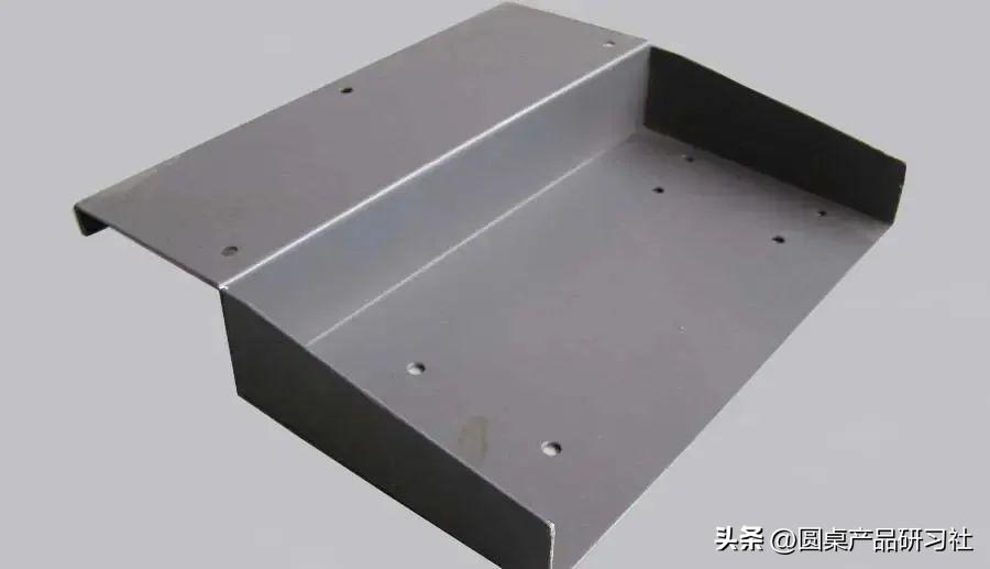
1、 Folding bed processing content: 1. L folding is divided into 90 degree folding and non 90 degree folding according to the angle.
According to processing, it can be divided into general processing (L>V/2) and special processing (L 1> The mold is selected based on the material, plate thickness, and forming angle. 2> The principle of reliance 1) Based on the principle of two rear positioning rules and positioning according to the shape of the workpiece. 2) When positioning a rear gauge, pay attention to deviation and ensure that it is on the same centerline as the bending size of the workpiece. 3) When bending small folds, it is better to process them in the reverse position. 4) It is better to set the rules towards the back and towards the middle. (When leaning against the position, it is not easy for the rear regulation to lift) 5) It is better to be close to the edge of the position and the rear regulation. 6) It is better to lean on the long side. 7) Use fixtures to assist in positioning (irregular inclined edge positioning). 3> , Precautions 1. Attention should be paid to the positioning method during processing and the standardized movement mode among various positioning processing methods. 2. When the mold is assembled, it should be bent and pulled back to prevent deformation of the workpiece during bending. 3. When bending large workpieces internally, due to the large shape of the workpiece and the small bending area, it is difficult for the cutting tool and the bending area to coincide, resulting in difficulty in positioning the workpiece or damage to the bent workpiece. To avoid the above situation, a positioning point can be added in the longitudinal direction of the machining, so that the machining can be positioned from two directions, making the machining positioning convenient and improving the machining safety, avoiding workpiece damage, and enhancing production efficiency. 2. N-fold requires different processing methods depending on the shape. When bending, the internal dimensions of the material should be greater than 4MM, and the size of the X dimension is limited by the shape of the mold. If the size inside the material is less than 4MM, special methods should be used for processing. 1> Choose the mold based on material thickness, size, material, and bending angle. 2> The principle of reliance 1) Ensure that the workpiece does not interfere with the tool 2) Ensure that the positioning angle is slightly less than 90 degrees. 3) It is best to use two rear positioning rules, except in special circumstances. 3> , Precautions 1) After bending L, the angle should be kept at or slightly less than 90 degrees to facilitate machining and positioning. 2) During the second folding process, it is required to align the position with the machining surface as the center. 3. Z-bend, also known as segment difference, refers to the bending of one positive and one negative. Divide the oblique edge segment difference and the straight edge segment difference according to the angle. The minimum size for bending processing is limited by the processing mold, while the maximum processing size is determined by the shape of the processing machine. In general, when the internal size of Z-folded material is less than 3.5T, segmented die processing is used. When it is greater than 3.5T, normal processing methods are used. 1> The principle of reliance 1) Convenient positioning and good stability. 2) Generally, the positioning is the same as the L fold. 3) The secondary positioning requires that the processed workpiece be flush with the lower mold. 2> , Precautions 1) The processing angle of the L fold must be in place, generally required to be between 89.5-90 degrees. 2) When pulling back according to the later specifications, attention should be paid to the deformation of the workpiece. 3) The order of processing must be correct. 4) For special processing, the following methods can be used: Center line separation method (eccentric machining) Small V processing (requires increasing bending coefficient) Easy to mold forming Grinding the lower mold 4. Reverse folding and flattening, also known as edge compression. The processing steps for dead edges are: 1. Bend and insert to a depth of about 35 degrees first. 2. Then flatten and mold until it is flat and tightly attached. 1> Method of Model Selection Select the V-groove width of the lower mold with a depth of 30 degrees according to 5-6 times the material thickness, and choose the upper mold according to the specific situation of processing dead edges. 2> , Precautions Attention should be paid to the parallelism of both sides of the dead edge. When the processing size of the dead edge is relatively long, the flattened edge can be folded at a raised angle first and then flattened. For shorter dead edges, padding processing can be used. 5. Pressing hardware uses a folding bed to press and seal hardware components, usually using auxiliary molds such as concave molds and fixtures for processing. In general, there are: compression nuts, compression bolts, compression screws, and other hardware components. Processing precautions: 1. When the shape of the workpiece needs to be avoided during machining, avoidance measures should be taken. 2. After processing, it is necessary to check whether the torque and thrust meet the standards, and whether the hardware and workpiece are flush and tightly attached. 3. After bending and pressing, when pressing next to the machine tool, pay attention to the machining avoidance and parallelism of the mold. 4. If it is bulging, it is also important to note that there should be no cracks on the bulging edge, and the bulging edge should not protrude above the surface of the workpiece. 6. The processing contents of easy molding generally include: small differences, hooks, bridges, bags, pressure springs, and some irregular shapes. The design principle of Easy Mold refers to the "Laser Cutting Easy Mold Design Principle" Easy to mold generally uses post positioning or self positioning. The most important thing in processing the above content with an easy mold is that its function and assembly requirements are not affected, and the appearance is normal 2、 Common problems and solutions in folding bed processing: 1. Analysis of the causes of sliding during processing: 1. When selecting a bending mold, a V-groove width of (4-6) T is generally chosen. When the size of the bend is less than half the width of the selected V-groove, a sliding phenomenon will occur. 2. The selected V-slot is too large 3. Process processing Solution method 1. Center line deviation method (eccentric machining). If the internal dimensions of the bent material are less than (4-6) T/2, make up for the difference as much as possible 2. Pad processing. 3. Bend with a small V-groove and apply pressure with a large V-groove. 4. Choose a smaller V-slot. 2. Analysis of the reasons why the internal bending width is narrower than the standard mold width: Due to the minimum standard width of the folding bed mold being 10MM, the bending processing part has a width of less than 10MM. If it is a 90 degree bend, its length dimension shall not be less than 2 (L+V/2)+T. For this type of bending, the mold must be fixed on the mold seat (except for unrestricted freedom in the upward direction) to avoid displacement of the mold, which may cause the workpiece to be scrapped or cause safety accidents. Solution: 1> Increase the size (to be coordinated with the customer), that is, increase the width of the internal fold. 2> Easy to mold processing 3> Grinding tools (which leads to an increase in processing costs) 3. The hole is too close to the bending line, and bending will cause the hole to pull the material. Analysis of the reasons for flipping: Assuming the distance between the hole and the bending line is L, when L<; At (4-6) T/2, the hole will pull the material. Mainly due to the stretching force during the bending process, the material undergoes deformation, resulting in the phenomenon of pulling and flipping. According to the existing standard mold groove width, the minimum L value for different plate thicknesses is shown in the following table: Solution: 1> Increase the size and grind the folded edges after forming. 2> Expand the hole to the bending line (must have no impact on appearance or function, and the customer agrees). 3> Cut line processing or pressure line processing 4> Mold eccentric processing 5> Modify the hole size 4. Analysis of the deformation reasons at the extraction point after bending due to the small distance L between the extraction edge and the bending line: When L<; At (4-6) T/2, due to the contact between the drawing and the lower mold, deformation occurs during the bending process due to the force exerted on the drawing. Solution: 1> Cut or press the line. 2> Modify the drawing size. 3> Using special molds for processing 4> Mold eccentric processing 5. Analysis of the causes of warping after flattening the long dead edge: Due to the long dead edge, it cannot adhere tightly when flattened, resulting in its end curling up after flattening. This situation is closely related to the flattened position, so attention should be paid to the flattened position when flattening Solution: 1> Before folding the dead edge, first fold the raised corner (as shown in the diagram), and then flatten it. 2> Flatten in multiple steps: Press the end first to bend the dead edge downwards. Flatten the roots. Attention: The flattening effect is related to the operator's operational skills, so please pay attention to the actual situation during flattening. 6. Analysis of the Reasons for the Easy Fracture of High Height Bridge Pulling: 1> Due to the high height of the bridge, the material was severely stretched, resulting in fracture. 2> The corners of the mold are not polished or not polished enough. 3> The toughness of the material is too poor or the bridge body is too narrow. Solution: 1> Extend the process hole on the side of the fracture. 2> Increase the width of the bridge. 3> Grind the R angle of the mold and increase the transition of the arc. 4> Add lubricating oil to the suction bridge. (Therefore, this method will make the surface of the workpiece dirty, so it cannot be used for AL parts, etc.) 7. Analysis of the reasons for the running of machining dimensions during easy mold processing: Due to the forward compression force exerted on the workpiece during the machining process, the workpiece moves forward, resulting in an increase in the small rake angle L at the front. Solution: 1> Grind off the shaded areas in the picture. Usually, the difference is made up as much as possible. 2> Grind off all the self positioning parts of the mold and switch to fixed positioning. (As shown in the figure below) 8. The overall size of the material (referring to unfolding) is too small or too large, which does not match the circular surface. Cause analysis: 1> The project was launched incorrectly. 2> The cutting size is incorrect. Solution: Calculate the allocated deviation for each bend based on the total deviation in the direction of deviation and the number of bending blades. If the calculated allocation tolerance is within the tolerance range, the workpiece is acceptable. If the size is too large, a small V-groove can be used for processing. If the size is too small, a large V-groove can be used for processing. 9. Analysis of the reasons for deformation caused by expansion or loose fit after hole punching and mortising: 1> Swelling is caused by the R angle of the hole punch being too small or the burrs on the flange being too large. 2> The loose fit is due to the inadequate expansion of the hole. 3> The deformation may be caused by hole misalignment or incorrect mating method. Solution: 1> Choose a punch with a large R-angle instead. Attention: Burrs around the hole during hole drawing and flanging. 2> Increase the pressure, enlarge and deepen the salad hole, and use a punch with a large R-angle instead. 3> The method of excavating the reasons for changing the mating method and hole misalignment. 10. Analysis of the causes of skewness or deformation of the workpiece after screw pressing: 1> During the processing of the product, there were no broken flat workpieces. 2> Uneven force or excessive pressure on the lower surface of the workpiece. Solution: 1> When pressing the screw, the workpiece should be leveled. 2> Make a support frame. 3> Adjust the pressure again. 4> Increase the range of force on the lower surface and decrease the range of force applied on the upper surface. 11. Analysis of the reasons for the non parallelism between the two sides after the segment difference: 1> The mold has not been calibrated. 2> The upper and lower mold gaskets are not adjusted properly. 3> The selection of upper and lower mold surfaces is different. Solution: 1> Re calibrate the mold. 2> Add or remove shims. (For specific adjustment methods, please refer to "Segment Processing Technology") 3> The mold is eccentric. 4> Replace the surface so that the surfaces of the upper and lower molds are the same. 12. Analysis of the reasons for the deep creases on the surface of the product: 1> The V-groove of the lower mold is small 2> The R angle of the V-groove in the lower mold is small 3> The material is too soft. Solution: 1> Using large V-groove processing 2> Using a mold with a large R-angle for processing 3> , cushion material bending (cushion steel sheet or Yuli glue) 13. Analysis of the causes of deformation near the bending point after bending: The machine runs fast during the bending process, and the upward bending speed of the workpiece during deformation is greater than the speed at which the operator supports the workpiece movement with their hands. Solution: 1> Reduce the operating speed of the machine 2> Increase the speed of the operator's hand support. 14. Analysis of the causes of cracking in AL parts during bending: Due to the unique crystal structure of AL material, it is prone to fracture when bent in parallel with the grain direction. Solution: 1> When cutting, consider rotating the AL material perpendicular to the bending direction (even if the bending direction of the material is perpendicular to the grain). 2> Increase the R angle of the upper mold.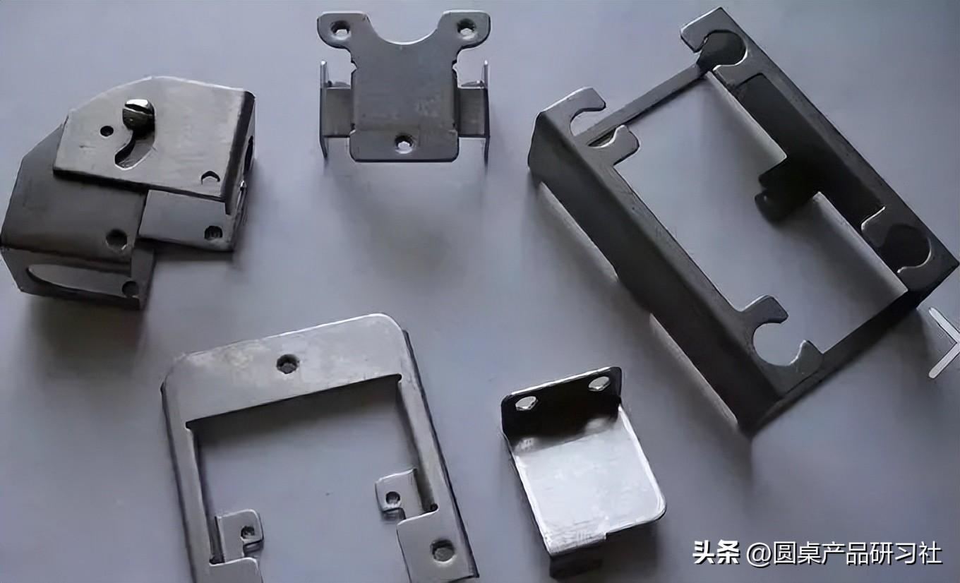


 Spanish
 Arabic
 French
 Portuguese
 Belarusian
 Japanese
 Russian
 Malay
Malay Icelandic
 Bulgarian
 Azerbaijani
 Estonian
 Irish
Irish Polish
 Persian
 Boolean
 Danish
 German
 Filipino
 Finnish
 Korean
 Dutch
Dutch Galician
 Catalan
 Czech
Czech Croatian
 Latin
Latin Latvian
 Romanian
 Maltese
 Macedonian
 Norwegian
 Swedish
 Serbian
 Slovak
 Slovenian
 Swahili
 Thai
Thai Turkish
 Welsh
Welsh Urdu
Urdu Ukrainian
 Greek
Greek Hungarian
 Italian
 Yiddish
 Indonesian
 Vietnamese
 Haitian Creole
 Spanish Basque

