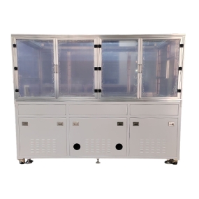
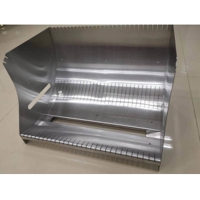
Shenzhen EMAR Precision Technology is dedicated to high-precision CNC Machining. We provide you with a detailed analysis of the drive structure and transmission system characteristics of CNC machine tools. Starting from the transmission pair, there are generally the following types of mechanical transmission pairs for ordinary machine tools:
1. Belt transmission: It relies on frictional force transmission. In addition to synchronous toothed belts, it has a simple structure, easy manufacturing, and low cost. It may slip during overload and can provide overload protection. The disadvantage of belt transmission is that it has sliding and cannot be used in situations where accurate speed ratios are required. Application example: The main motor drives the lathe spindle.
2. Gear and rack transmission: The gears rotate, while the racks move in a corresponding straight line. Application example: Heavy duty gantry feed shaft drive.
3. Gear transmission: With a simple and compact structure, it can transmit large torque and adapt to variable speeds and loads, making it the most widely used. Its disadvantage is that the line speed cannot be too high. Gear transmission is currently the most widely used transmission method in machine tools. Application example: High torque spindle transmission mechanism.
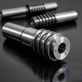
4. Worm gear transmission: The worm gear is the active component that transmits its rotation to the worm gear. This transmission method can only be driven by a worm to rotate the worm wheel, otherwise it is impossible. Application example: Rotary mechanism of horizontal milling machine worktable.
5. Thread transmission: Spiral transmission, a mechanical transmission that uses the engagement of screws and nuts to transmit power and motion. Mainly used to convert rotational motion into linear motion and torque into thrust. Application example: Screw drive, commonly used for threading in vehicles.
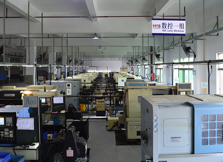
EMAR walking CNC lathe machining workshop
The commonly used transmission pairs for CNC machine tools include the five types that have been accumulated over a long period of time. With the advancement of technology, CNC machine tools have begun to pursue high speed, high precision, and high rigidity, giving rise to a number of advanced transmission pairs.
1. Linear motor: It is a transmission device that directly converts electrical energy into linear motion mechanical energy without the need for any intermediate conversion mechanism. It can be seen as a rotating motor that is cut radially and flattened into a plane. Some horizontal machining centers now use motor-driven rotary workbenches.
2. Elastic coupling: This is relatively traditional, using parallel or spiral groove systems to adapt to various deviations and accurately transmit torque. Elastic couplings usually have good performance and price advantages. In many practical applications of stepper and servo systems, elastic couplings are the preferred product. The integrated design enables the elastic coupling to transmit torque with zero clearance.
3. Electric spindle: The emergence of electric spindle has eliminated pulley transmission and gear transmission in the main transmission system of high-speed CNC machine tools. The spindle of the machine tool is directly driven by an internal electric motor, which shortens the length of the main transmission chain of the machine tool to zero, achieving "zero transmission" of the machine tool.
4. Roller cam mechanism: The cam divider is a mechanism that achieves intermittent motion, with significant characteristics such as high indexing accuracy, smooth operation, large torque transmission, self-locking during positioning, compact structure, small volume, low noise, good high-speed performance, and long service life. Application and workbench exchange or tool changing mechanism.
From the above products, it can be seen that the current transmission system has incomparable high speed, high precision, low friction, and less clearance.

EMAR Precision Technology Machining Center Workshop


 Spanish
 Arabic
 French
 Portuguese
 Belarusian
 Japanese
 Russian
 Malay
Malay Icelandic
 Bulgarian
 Azerbaijani
 Estonian
 Irish
Irish Polish
 Persian
 Boolean
 Danish
 German
 Filipino
 Finnish
 Korean
 Dutch
Dutch Galician
 Catalan
 Czech
Czech Croatian
 Latin
Latin Latvian
 Romanian
 Maltese
 Macedonian
 Norwegian
 Swedish
 Serbian
 Slovak
 Slovenian
 Swahili
 Thai
Thai Turkish
 Welsh
Welsh Urdu
Urdu Ukrainian
 Greek
Greek Hungarian
 Italian
 Yiddish
 Indonesian
 Vietnamese
 Haitian Creole
 Spanish Basque

