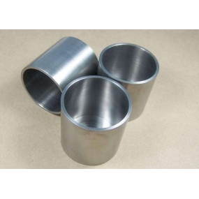
Non standard cabinets are generally used in places with special needs, and their size is different from that of standard chassis. In their customization, a relatively important component is the fixed tray, which is mainly used to install various equipment. There are many sizes available, and it is usually used to place 19; Standard tray, not 19“ And multiples refer to non-standard fixed trays, which are also what we call non-standard cabinets.
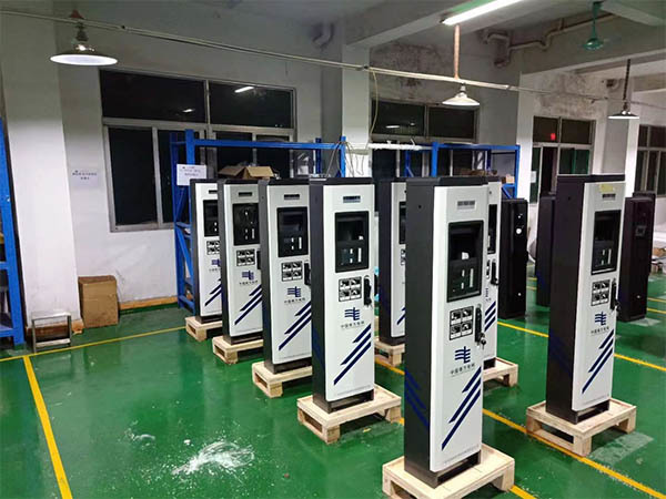
The advantages of customized non-standard cabinet are that its material is welded together, the frame degree is relatively high, the body size is relatively large, and it can store a large number of equipment. It has good ventilation, which can help the equipment inside the power cabinet dissipate heat, improve the heat dissipation performance of the power cabinet, and can be used for power distribution. It is a customized cabinet that does not meet standard production, so it can better meet the needs of users. It is widely used in industries such as instruments, meters, electronics, communication, automation, sensors, industrial control, and machinery.
What are the precautions for using non-standard cabinets? Below is an introduction for everyone.
1. Shielding. To reduce lightning electromagnetic interference, the steel bars and metal floors of the communication room and communication dispatch complex building should be welded to each other to form an equipotential Faraday cage. A metal shielding mesh should be laid on all six sides of the communication room, and the shielding mesh should be uniformly connected to the circular grounding bus in the room at multiple points. The 380V power supply of the overhead power line should be led down from the distribution transformer and replaced with a shielded cable before being led indoors. Outdoor communication cables should use shielded cables, and both ends of the shielding layer should be grounded. For cables with both armor tape and shielding layer, the armor tape and shielding layer should be grounded simultaneously indoors, while only the shielding layer should be grounded at the other end. Before entering the room, the cable should be buried horizontally for at least 10 meters, and the burial depth should be greater than 0.6 meters Non shielded cables should be buried horizontally in galvanized iron pipes for more than 10 meters, and both ends of the iron pipes should be grounded. If a varistor is added between the power line and the iron pipe at the entrance for outdoor activities, the lightning protection design effect will be better.
2. Its lightning protection and grounding requirements are essential basic guarantees for modern communication networks. Lightning protection grounding should be systematic and complete, taking into account both the lightning protection measures for the building and ground network, as well as the lightning protection measures for the grounding of the ground wire of the outdoor/outdoor power supply integrated communication cabinet equipment, and the lightning protection of external cables. Only in this way can we be confident that good grounding of the communication building's lightning protection outdoor/outdoor power supply cabinet is a crucial part of lightning protection. The smaller the grounding resistance value, the lower the overvoltage value. Therefore, under the premise of reasonable economic development, efforts should be made to reduce the working grounding resistance as much as possible.
3. All types of grounding wires should follow the principles of short, straight, and sufficiently large cross-sectional area, and should be able to meet the requirements of large fault currents (generally 35-95mm2 copper wire). The cross-sectional area of the grounding collection line is generally not less than 120mm2 copper wire or galvanized flat steel with the same resistance. It is required that all terminals ensure good contact, and the copper and iron are welded. The length of the steel bar welding interface should be greater than 6 times the diameter, and both sides should be welded through and treated with anti-corrosion. The copper terminals and terminals should be galvanized.


 Spanish
 Arabic
 French
 Portuguese
 Belarusian
 Japanese
 Russian
 Malay
Malay Icelandic
 Bulgarian
 Azerbaijani
 Estonian
 Irish
Irish Polish
 Persian
 Boolean
 Danish
 German
 Filipino
 Finnish
 Korean
 Dutch
Dutch Galician
 Catalan
 Czech
Czech Croatian
 Latin
Latin Latvian
 Romanian
 Maltese
 Macedonian
 Norwegian
 Swedish
 Serbian
 Slovak
 Slovenian
 Swahili
 Thai
Thai Turkish
 Welsh
Welsh Urdu
Urdu Ukrainian
 Greek
Greek Hungarian
 Italian
 Yiddish
 Indonesian
 Vietnamese
 Haitian Creole
 Spanish Basque

