① Introduction to G32 machining end face threads:
Overview: The end face threads are mostly rectangular threads, and the self centering chuck (disc thread) of the lathe uses this structure. This type of thread does not have a specific code annotation, usually a text annotation.
Figure 2-8 is a schematic diagram of the end face thread
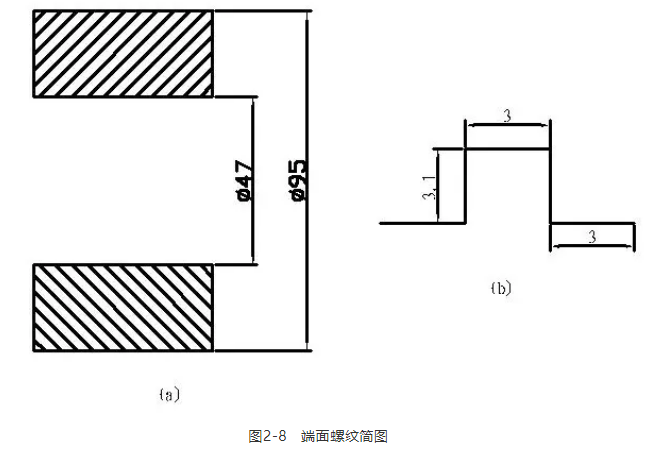
Figure (a) is a schematic diagram of the overall structure of the end face thread, while Figure (b) is a partial enlarged view of the end face thread. It is specified that when the thread depth is less than 5mm, an additional 0.1mm needs to be added.
Determination of end face thread rotation direction:
In the case of the main spindle turning forward, turning from the outside to the inside belongs to right-handed (clockwise), and vice versa is left-handed thread (counterclockwise).
Instruction format: G32 X-F_ (X is the coordinate of the cutting end point, F is the lead of the thread)
Program statement (only the threaded section of the end face)
G99 M3 S500 T0202; (Slot cutter B=3mm)
G0 X100 M8;
Z-0.5;
G32 X40 F3.0;
G0 Z3;
X100;
Z-0.7;
G32 X40. (Considering blade width diagram 2-9) F3.0;
G0 Z3;
X100;
Z-1.0;
G32 X40 F3.0;
G0 Z3;
X100;
Z-1.5;
G32 X40 F3.0;
G0 Z3;
X100;
Z-2.0;
G32 X40 F3.0;
G0 Z3;
X100;
Z-2.5;
G32 X40 F3.0;
G0 Z3;
X100;
Z-3.1;
G32 X40 F3.0;
G0 Z90;
M5;
M30;
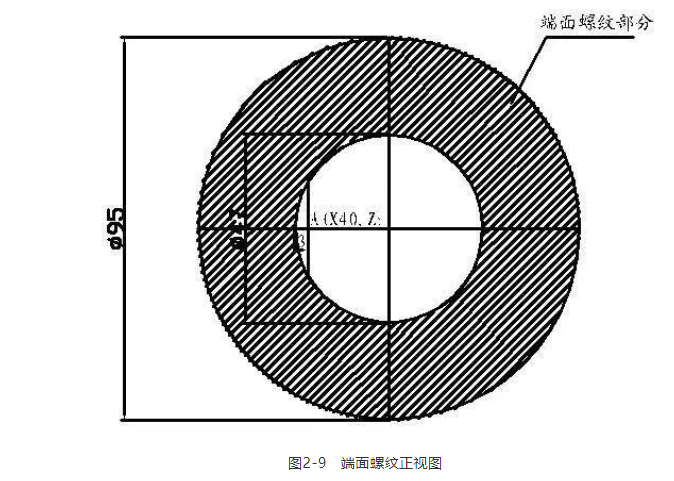
Note: The positioning should be consistent these times.
② Introduction to Variable Pitch Thread Processing
Some domestic CNC systems, such as Guangzhou CNC (GSK), use G32 instructions when machining variable pitch threads. As shown in Figures 2-10:
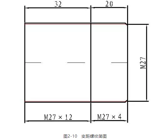
Figure 2-10 Schematic diagram of variable pitch thread
Numerical calculation:
The tooth height (diameter value) of M274 is 1.34=5.2mm;
The tooth height (diameter value) of M2712 is 1.312=15.6mm;
The tooth height is based on the minimum tooth height:
So the minor diameter is 27-5.2=21.8mm.
When turning variable pitch threads, the spindle speed is determined by the maximum thread pitch (P=12).
Program statement (only threaded section)
G99 M3 S200 T0202;
G0 X30;
Z3;
X26;
G32 Z-20 F4.0;
G32 Z-56 F12;
G0 X30;
Z3;
X25.6;
G32 Z-20 F4.0;
G32 Z-56 F12;
;
G32 X30;
Z3;
X21.8;
G32 Z-20 F4;
G32 Z-56 F12;
G0 X30;
Z90;
M5;
M30;
The so-called variable pitch thread refers to a specified reference pitch value F starting from the thread cut in, and then generating a pitch difference K (increase or decrease) every other pitch
In some imported CNC systems such as FANUC, there is a specific instruction G34 for machining variable pitch threads.
Instruction format: G34 X_Z_F_K_;
Among them, X and Z are the endpoint positions of the thread, F is the lead in the long axis direction at the starting point, K is the increase and decrease of lead per spindle rotation, and the command range of K value is 0.0001-500.000mm, as shown in the following figure.
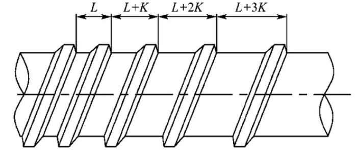
For example, the starting lead is 5mm, the lead increment is 1mm, the thread length is 50mm, and the program is G34 Z-50 F5. K1.
③ Processing of multi thread threads
Multi line threads are generally used for transmission and are straight threads. CNC Machining of multi line threads can be done by calling subroutines using G92. Imported machine tools also support G32 instructions for machining multi line threads, and G76 instructions can also be used for machining multi line threads (as discussed later).
G92 calls subroutines to process multi thread machining as shown in Figure 2-11.
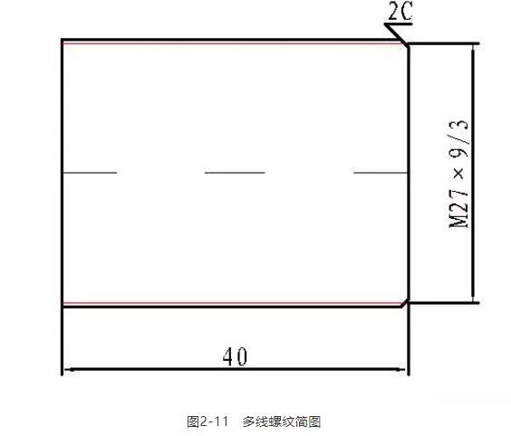
The meaning indicated in the figure: M279/3
Among them, M27 is the nominal diameter, 9 is the thread lead, and 3 is the pitch.
Because: lead=number of pitch lines, therefore: this is a three wire thread.
Numerical calculation:
Major diameter=27-0.133=26.61mm;
Minor diameter=27-1.33=23.1mm;
Program statement (only threaded section)
Subprogram (O0046)
G92 X26 Z-40 F9;
X25.7;
X25.4;
X25.2;
X25.0;
;
X23.1;
M99;
main program
G99 M3 S700 T0202;
G0 X30 M8;
Z3;
M98 P0046;
G0 X30;
Z6;
M98 P0046;
G0 X30;
Z9;
M98 P0046;
G0 Z90;
M5;
M30;
Z3. Z6. Z9. Increase one pitch per positioning (P=3)
Some systems also support G32 machining of variable pitch threads
Instruction format: G32 X_Z_F_Q_;
Where X and Z are the endpoint positions of the thread, F is the thread lead, and Q is the starting angle of the thread. Increment is 0.001, decimal point cannot be specified; If processing double thread and the corresponding displacement is 180, specify Q180000
The starting angle Q is not a modal value and must be specified each time, otherwise the system will consider it to be 0
Multi thread machining is effective for G32, G34, G92, and G76 instructions.
④ Processing of trapezoidal threads
On CNC lathes, G76 thread cutting cycle instructions can be used to machine trapezoidal threads using methods such as oblique and staggered cutting, but there are certain technical difficulties. Therefore, based on long-term practical experience, a set of precise calculations of programming data using a series of empirical formulas has been developed. By using thread cutting instructions G32 and calling subroutines, and cleverly setting machining methods in the subroutines, qualified trapezoidal threads can be safely and reliably processed.
Analysis of programming and machining skills:
(1) When grinding the blade, pay attention to ensuring that the cutting edge angle of the turning tool is consistent with the tooth shape angle, and the width of the cutting edge must be less than the width of the groove bottom.
(2) Try to make the gap between the teeth during the turning process large enough to ensure smooth chip removal with a single cutting edge of the turning tool. It is advisable to have a trapezoidal thread groove bottom width of 1.7mm with a pitch of 5mm and a sharpened blade tip of 1.2-1.4mm. Excessive blade tip can cause the gap between the blade tip and the tooth side to be too small, making it difficult to remove debris and prone to cutting; A too small tool tip can cause a decrease in the rigidity of the tool tip, which can easily cause vibration and result in poor machining surface roughness, making it difficult to control accuracy.
(3) Pay attention to the positioning of the turning tool before turning the thread. The distance from the tool tip to the tooth top should be greater than the tooth height h. If it is less than the tooth height h, it will cause friction between the tool tip and the thread tooth top during the post threading stage, resulting in waste.
(4) Develop and call subroutines, which can use either a single subroutine or multiple subroutines.
1. Calculation of programming data
(1) The positioning point X value of the blank=nominal diameter+(0.5P+ac) 2+1, where P is the pitch, ac is the tooth tip clearance, and 0.5P+ac is the tooth height. Choose the value of the tooth tip gap based on the size of the pitch, as shown in the table below.

(2) First cutting point X value, X=nominal diameter - average deviation of upper and lower parts -0.2
(3) Minor diameter=nominal diameter - (0.5P+ac) 2
(4) Processing addend=(X-value of the first cutting point - minor diameter)/X-direction feed amount (diameter value)+1
(5) U=X value of the blank positioning point - X value of the first cutting point.
2. Cutting route: Generally, the left and right cutting method is used to process trapezoidal threads, and those with small pitches can be divided into coarse turning, semi precision turning, and precision turning; The ones with large pitches can be divided into coarse turning, semi coarse turning, semi precision turning, and precision turning. Using the left and right cutting method, when calling the subroutine once, the turning tool enters a cutting depth and moves one gap to the right after turning one tool on the left, and then turns another tool. When calling the subroutine again, the turning tool enters another cutting depth and moves one gap to the right after turning one tool on the left, and then turns another tool until it is completed.

[Example of trapezoidal thread machining] As shown in the figure below, it is a trapezoidal thread machining part.
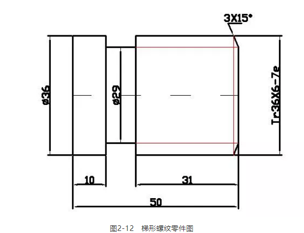
3. Calculation of data for machining trapezoidal threads
(1) Rough positioning point X value
X=nominal diameter+(0.5P+ac) 2+1=36+(0.56+0.5) 2+1=44
(2) Check the table to determine the upper and lower deviation values of the nominal diameter: the upper deviation is 0, the lower deviation is -0.375, and the average value is -0.2. The X value of the first cutting point is 36-0.2-0.2=35.6
(3) Minor diameter=nominal diameter - (0.5P+ac) 2=36- (0.56+0.5) 2=29.
(4) Processing addend=(X-value of the first cutting point - minor diameter)/X-direction feed amount (diameter value)+1=(35.9-29)/0.1+1=67
(5) U=Rough positioning point X value - First cutting point X value=44-35.6=8.4
4. Calculate the size of the trapezoidal thread and check the table to determine its tolerance
Major diameter D=36
According to the table, the tolerance of d is determined as d-0.5p=36-3=33, so d=33
Tooth height h=0.5p+ac=3.5
Minor diameter d=d, medium -2h=29
Crown width f=0.336p=2.196
Tooth base width w=0.366p 0.536a=2.196-0.268=1.928
Based on experience, it is reasonable to use a trapezoidal thread with a tool tip width of f=1.5mm.
Using a 3.1mm measuring rod to measure the middle diameter, the measurement dimension M=d+4.864d-1.866p=36.88, and the tolerance (0-0.355) is determined based on the middle diameter tolerance zone, resulting in M=36.525-36.88
5. Write CNC programs
G99 M3 S300 T0101;
G0 X44 Z8; (44 is the X value of the blank positioning point)
M8;
M98 P470002; (47 is the number of rough machining tools)
M98 P200003; (20 is the number of precision machining tools)
M9;
G0 X100 Z100;
M30
Write rough machining subroutines
O0002
G0 U-8.4; (8.4 is the U-value)
G32 Z-37 F6;
G0 U8.4;
Z7.7;
U-8.4;
G32 Z-37 F6;
G0 U8.4;
Z8.3;
U-8.4;
G32 U0 Z-37 F6;
G0 U8.3;
Z8;
M99;
Writing precision machining programs
O0003;
G0 U-8.4;
G32 Z-37 F6;
G0 U8.4;
Z7.9;
U-8.4;
G32 U0 Z-37 F6;
G0 U8.4;
Z8.1;
U-8.4;
G32 U0 Z-37 F6;
G0 U8.3;
Z8;
M99;
The above-mentioned workpiece can also be programmed using G92 subroutines.
main program
G00 X44 Z6; (Thread cutter quickly reaches diameter) Φ 44mm End Face Outer 3mm)
M98 P60002; (Coarse car calls O0002 subroutine 6 times)
M98 P80003; (Half rough car calls O0003 subroutine 8 times)
M98 P80004; (Semi precision car calls the main program O0004 subroutine 8 times)
M98 P80005; (Fine car calls O0005 subroutine 8 times)
G0 X100 Z100; (Thread cutter quickly returns to the starting point of the program)
O0002 (Rough car subroutine)
G00 U-0.5; (Rough turning with each feed depth)
M98 P0006; (Calling the basic subroutine O0006)
M99; (The subroutine ends and returns to the main program)
O0003; (Semi rough car subroutine)
G00 U-0.3; (Semi rough turning with each feed depth)
M98 P0006; (Calling the basic subroutine O0006)
M99; (The subroutine ends and returns to the main program)
O0004; (Semi precision car subroutine)
G0 U-0.15; (Semi precision turning with each feed depth)
M98 P0006; (Calling the basic subroutine O0006)
M99; (The subroutine ends and returns to the main program)
O0005 (precision car subroutine)
G0 U-0.05; (Precision turning with each feed depth)
M98 P0006; (Calling the basic subroutine O0006)
M99; (The subroutine ends and returns to the main program)
O0006 (Basic subroutine)
G92 U-8 Z-37 F6; (Turning the left side of the thread)
G00 W0.43; (The threaded knife quickly moves 0.43mm to reach the side of the right tooth)
G92 U-8 Z-37 F6; (Turning the right side of the thread)
G0 W-0.43; (Move -0.43mm to return to the axial position on the left side of the thread)
M99; (The subroutine ends and returns to the main program)
Can we give it some attention before we leave? Update UG programming videos every day.


 Spanish
 Arabic
 French
 Portuguese
 Belarusian
 Japanese
 Russian
 Malay
Malay Icelandic
 Bulgarian
 Azerbaijani
 Estonian
 Irish
Irish Polish
 Persian
 Boolean
 Danish
 German
 Filipino
 Finnish
 Korean
 Dutch
Dutch Galician
 Catalan
 Czech
Czech Croatian
 Latin
Latin Latvian
 Romanian
 Maltese
 Macedonian
 Norwegian
 Swedish
 Serbian
 Slovak
 Slovenian
 Swahili
 Thai
Thai Turkish
 Welsh
Welsh Urdu
Urdu Ukrainian
 Greek
Greek Hungarian
 Italian
 Yiddish
 Indonesian
 Vietnamese
 Haitian Creole
 Spanish Basque

