For enterprises engaged in precision machining, it should be clear that the process specification is the main technical document for the processing of aviation components. It specifies the process and sum of processing raw materials into qualified parts. Generally, the content of the process specification process chart includes equipment information, process equipment information, processing requirements, and operation steps. Production operators only need to process the parts according to the order of the process chart in the process specification and the content in the process chart to process the raw materials into products that comply with the design drawings of Tonghu.
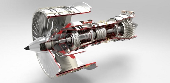
With the update and iteration of aviation engines, the energy and reliability of engines are gradually improving. A single bright sword has more functions, and the structure of parts is becoming increasingly complex. The precision required for design is also increasing year by year. The traditional process specification model is no longer sufficient to meet the design requirements of engine components, as well as the production needs of high efficiency, high quality, and low cost. It is also not suitable for CNC Machining and information management. Exploring new process specification models and improving the current process specification situation are important issues that many engine component processing and technical personnel need to consider.
1、 Analysis of the Current Status of Component Processing Technology Regulations
The traditional mode of process specification is very simple, and the operation steps are not detailed enough. There are many uncertain factors that cannot guide the construction personnel well. Different operators have different introductions to the content of the process specification. The product quality and processing efficiency mostly depend on the operator. Compared with the international advanced aircraft engine process specification mode, the gap is still quite obvious.
In the process specification, each processing step has a corresponding process chart. The traditional mode of process chart is relatively simple. The process chart mainly includes the schematic diagram of part processing, work content, the number of clamping molds, cutting tools, measuring tools used, the size and technical requirements that should be met after processing, and the matters that need to be noted. Taking the turning process as an example, Figure 1 is a chart of the part turning process. The sketch on the left is a schematic diagram of the machining process, usually represented by a two-dimensional view. The thick solid line represents the surface that needs to be machined, the thin solid line represents the non machined surface, and the uppercase letters A, B, C, etc. represent the positioning reference, support surface, clamping or pressing surface of the part. In the schematic diagram, dimension lines are used to indicate the dimensional and positional tolerances that should be ensured after the machined surface is completed. Each dimension and positional tolerance is marked with a sequence number. The job content column on the right usually consists of three parts. The first part is about the alignment requirements before processing. It usually requires the alignment fixture to locate the surface, radial surface, and axial surface of the part, and specifies the maximum allowable runout value; The second is the content of turning processing in this process, usually represented by size sequence numbers, corresponding to the sequence numbers in the machining diagram; The third is the requirement for form and position tolerances after turning, which corresponds to the sequence number in the machining diagram.
1. Current situation of process specifications
Each machining process in the process specification has a corresponding process chart. The traditional mode of process chart is relatively simple. The process chart mainly includes the machining schematic diagram and work content of the components, the fixtures, molds, cutting tools, measuring tools, etc. used, the dimensions and technical requirements that should be met after completing the machining, and the key points that need to be noted.
2. Analysis of the Current Status of Process Regulations
1) Preparation analysis before processing
Before processing, operators usually read the process chart. If it is a CNC machining process, they also need to read the CNC step card. Workers prepare the process equipment according to the process chart. For the general process equipment used in the process, as most process documents do not have clear provisions, workers will prepare based on their own insights and experience and the existing process equipment conditions in the production workshop. When choosing general cutting tools, workers may be unclear about the cutting performance of parts and tool materials, and may be limited by the production workshop's tool reserves. Workers may choose tools arbitrarily, and the selected tool materials and geometric dimensions may deviate. The cutting parameters used may be unreasonable, resulting in unstable surface quality and dimensional accuracy of parts processing, unstable part processing costs and cycles. The sentence is:, Inaccurate tool consumption statistics make production preparation and implementation of production plans difficult. Similarly, when workers choose measuring tools, the measurement methods they use may also be inaccurate, and the accuracy of the selected measuring tools may not match the accuracy of the measured dimensions, resulting in inaccurate measurement results.
2) Installation analysis of fixtures and parts
For example, when installing fixtures and parts, the axis of the parts should be as consistent as possible with the rotation center of the machine tool's worktable, and the cross section machine of the parts should be as perpendicular as possible to the rotation center of the machine tool's worktable, in order to ensure the mutual position requirements between the various surfaces of the parts after processing. For parts that require high design accuracy, have relatively large dimensions, and are prone to deformation, the installation, calibration, and clamping steps of fixtures and parts are crucial, which will have a significant impact on the machining accuracy of the parts. Due to the lack of installation views and operation steps for fixtures and parts in the process specification, machining personnel can only install fixtures and parts according to the process chart, sketch, and simple calibration requirements in the work content column, The process specification requires that the runout of the inner hole of the part should not exceed 0.05mm before processing. Due to the lack of clear point correction and continuous correction, workers may adopt point-to-point correction or continuous correction during the operation process. Point to point calibration requires a relatively short time and is easy to achieve, but the calibration results are not accurate. Continuous calibration requires a long time and is also difficult, but the calibration results will be more accurate. The two calibration methods will lead to essential differences in the machining results of the components. For the compression of parts, the process specification only specifies the use of pressure plates to compress the parts, without specifying the implementation steps, the magnitude of the compression force, and the precautions to be taken. Workers generally operate according to their own experience and habits, resulting in excessive or uneven compression force, which may cause damage or deformation to the parts.
3) Process analysis of processing
When cutting parts, workers process them according to the size numbers in the job content column and the corresponding dimensions in the sketch. For cutting processes, workers arrange the machining sequence, cutting path, and cutting parameters of the part surface based on their own machining experience and habits. For CNC machining processes, CNC programmers arrange the above content based on their own process experience and habits. Due to the limitations and habitual thinking of machining personnel and CNC programmers in mastering mechanical machining technology, when arranging the machining sequence, cutting path, and cutting parameters of the part surface, they generally consider more whether it is convenient to process, and less consider the differences in part structure, the impact of tool life, and the influence of cutting force and cutting force on part machining deformation. If there are a large number of surfaces that need to be machined in one process, the changes in internal stress of the part will be different when the machining process of the machined surface is different. When the cutting path is different, the cutting force and cutting stress generated will be different, and the degree of tool wear and deformation of the part will also be different. The sentence is:; When the cutting parameters are different, the magnitude of cutting force, tool wear, machining quality of the part surface, and machining deformation of the part also vary.
Process specification sketches usually use two-dimensional views. For rotating parts and structurally simple parts, two-dimensional views can clearly express the structural shape of the parts. However, for parts with complex design mechanisms, surface designs with grooves, protrusions, and hole systems, or non rotating parts, they are generally machined on multi axis CNC machining centers, and two-dimensional views cannot clearly express these structural shapes and positional relationships.
2、 Suggestions for improvement measures of process specifications
The improvement of the process specification mode is not just a simple improvement of the process table style, but a complex system engineering of multi-faceted improvement of the processing technology. The following are suggestions for the improvement measures of the process specification mode:
1. Refine the installation and adjustment of fixtures and parts
In the process diagram of the process specification, a schematic diagram of the installation of fixtures and parts should be drawn, detailing the operation methods and specific steps for fixture and part installation, calibration, and clamping, so that any worker can operate according to the process specification without any differences. The process specification for fixture and part installation in the part turning process specifies the operation steps:
1) Use an oilstone to remove protrusions, burrs, and bumps on the working surface of the machine tool, as well as on the ground of the pad. Wipe clean with a clean cloth, place the pad on the working surface of the machine tool, align the radial runout and end face runout of the center cylinder of the pad within the specified values, and use an oilstone to remove protrusions and burrs on the upper end face of the pad;
2) Lift the fixture with the designated crane, remove any protrusions or burrs on the installation ground with an oilstone, wipe it clean with a clean cloth, place the fixture on top of the pad, visually align the center, use the specified number of bolts to gently connect the fixture and pad, align the radial runout and end face flatness of the fixture within the specified values, tighten the bolts to fix the fixture to the worker, and then recheck that the radial and end face runout of the fixture should not exceed the specified values;
3) Wipe the front end face of the part and the positioning surface of the fixture clean with a cloth, check for protrusions, burrs, etc., place the part on the fixture, align the inner hole of the part and the jumping of the end face within the specified value, adjust and tighten the axial shaft support during the process, then use the specified number of pressure plates to press the part tightly, and then use a dial gauge to check that the surface movement during axial compression is within the specified value;
4) Gently tighten the radial anti movement bolts on the outer surface of the parts, without allowing them to move.
2. 3D machining view
With the continuous increase and update of CNC equipment in various aviation enterprises, multi axis CNC machining centers have been widely used for complex milling and hole machining processes. The machining process is mainly controlled by CNC programs. If the machining sketch of the process specification still uses a two-dimensional view, it cannot intuitively express the structural shape of the machining supplement and the positional relationship between each machining part. Changing to a three-dimensional view can clearly display the shape and position of the machining part, which is beneficial for operators to understand the machining content and inspect the machining process;
3. Plan the surface processing sequence and cutting path
In many cases, there are two or more machining surfaces in a process, and each machining surface is not machined in one go. Therefore, in the process chart sketch, the number of times each surface needs to be machined should be indicated, and each cutting should be standardized with a serial number. The serial number should be marked according to the cutting sequence of the process planning, and the cutting sequence should be clearly filled in the work content column. The thin solid line with arrows in the sketch indicates the path and direction of each cutting. When determining the cutting sequence of each surface and planning the cutting path and direction, the principles followed should be conducive to controlling the deformation that occurs during part machining, extending the life of certain surface machining tools, and controlling the process, so that the machining quality, machining cost, and machining cycle are relatively stable;
4. Resources for improving process information
1) Cancel the CNC step card and integrate the CNC program information and tool information from the CNC step card into the process specification. This can effectively reduce the difficulty of process file management and also eliminate the complexity of workers needing to borrow both the process specification and the CNC step card at the same time;
2) Improve the information of cutting tools and measuring tools. In addition to the special cutting tool numbers marked in the process chart, the information of general cutting tools should also be indicated. For CNC machining processes, the selection view and size requirements of the tool holder, tool holder, and blade for each set of cutting tools should be drawn, and the numbers of the tool holder, tool holder, and blade equipped should be indicated. The position number of each set of cutting tools in the machine tool magazine should also be marked. In addition to the special measuring tool numbers marked in the process chart, the information of general measuring tools should also be marked;

Summary
In recent decades, the mode of processing technology regulations for domestic aviation engine components has not undergone significant changes, and there is still a lot of room for improvement compared to international advanced technology regulations. In the past decade, many domestic aviation engine enterprises have cooperated with international advanced aviation engine enterprises to carry out subcontracting production, and design projects for disk ring parts, sheet metal welding parts, casing parts, etc. If the advanced management methods and processing technologies mastered in these subcontracting cooperation can be quickly applied to the research and production of domestic aviation products, it will accelerate the pace of domestic aviation engine development.
Shenzhen EMAR Precision Technology Co., Ltd. focuses on high-precision CNC machine tools for external processing. Currently, our company is equipped with CNC equipment including center of gravity CNC lathes, tool walking CNC lathes, turning milling composite machining centers, and CNC vertical machining centers. More than 100 CNC equipment can meet the customization and batch processing tasks of precision parts. Our product range covers aviation parts, automotive parts, medical parts, communication parts and other series. The company has more than 20 years of precision machining experience and can ensure the accuracy and timely delivery of products. Welcome to call us, and we will be dedicated to serving you.


 Spanish
 Arabic
 French
 Portuguese
 Belarusian
 Japanese
 Russian
 Malay
Malay Icelandic
 Bulgarian
 Azerbaijani
 Estonian
 Irish
Irish Polish
 Persian
 Boolean
 Danish
 German
 Filipino
 Finnish
 Korean
 Dutch
Dutch Galician
 Catalan
 Czech
Czech Croatian
 Latin
Latin Latvian
 Romanian
 Maltese
 Macedonian
 Norwegian
 Swedish
 Serbian
 Slovak
 Slovenian
 Swahili
 Thai
Thai Turkish
 Welsh
Welsh Urdu
Urdu Ukrainian
 Greek
Greek Hungarian
 Italian
 Yiddish
 Indonesian
 Vietnamese
 Haitian Creole
 Spanish Basque

