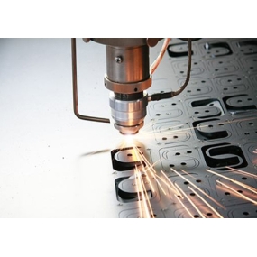
Mainly explain the functions of each button on the operation panel of the machining center, so that students can master the adjustment of the machining center, the preparation work before processing, and the methods of program input and modification. Finally, taking a specific component as an example, the basic operation process of machining parts on a machining center was explained, giving students a clear understanding of the operation of machining centers.
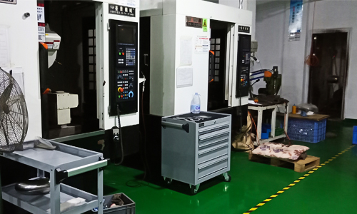 1 Processing requirements
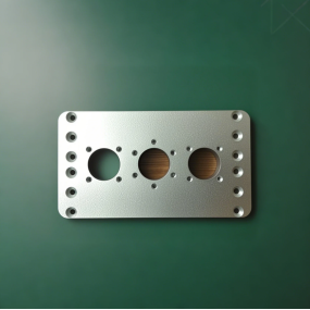
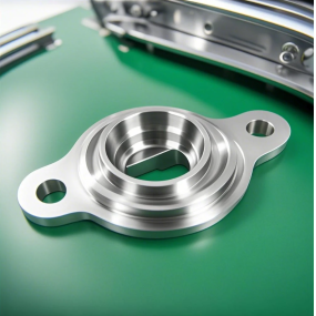
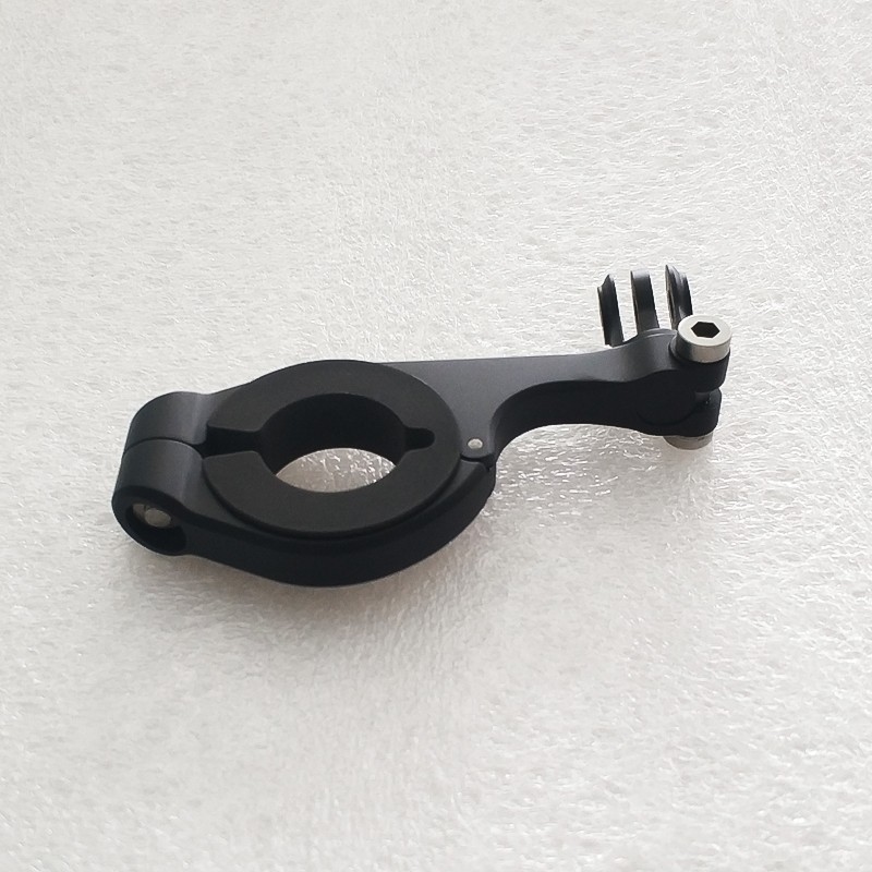
Process the parts as shown in the following figure. The material of the component is LY12, produced as a single piece. The blank of the part has been machined to size.
Equipment selection: V-80 machining center
2 Preparation work
Complete relevant preparation work before processing, including process analysis and route design, selection of cutting tools and fixtures, programming, etc.
 3 Operation steps and content
1. Power on, manually return each coordinate axis to the machine origin
2. Tool preparation
Select a Φ 20 end mill, a Φ 5 center drill and a Φ 8 Fried Dough Twists drill respectively according to the processing requirements, and then clamp the Φ 20 end mill with the spring collet handle. The tool number is set as T01, and clamp the Φ 5 center drill and Φ 8 Fried Dough Twists drill with the drill collet handle. The tool number is set as T02 T03, Install the edge finder tool on the spring-loaded chuck handle, and set the tool number to T04.
3. Manually place the tool holder, which has already been clamped, into the tool magazine
1) Enter "T01 M06" and execute
2) Manually install T01 tool onto the spindle
3) Follow the above steps to place T02, T03, and T04 into the tool magazine in sequence
4. Clean the workbench, install fixtures and workpieces
Clean the flat mouth vise and install it on a clean workbench. Use a dial gauge to align and level the vise, and then install the workpiece onto the vise.
5. Set the tool, determine and input the parameters of the workpiece coordinate system
1) Use an edge finder to align the tool and determine the zero bias values in the X and Y directions. Adjust the zero bias values in the X and Y directions
Input into the workpiece coordinate system G54, where the zero offset value in the Z direction is set to 0;
2) Place the Z-axis setter on the upper surface of the workpiece, call out No. 1 tool from the tool magazine and install the spindle, use this tool to determine the Z-direction zero offset value of the workpiece coordinate system, and input the Z-direction zero offset value into the length compensation code corresponding to the machine tool. The "+" and "-" numbers are determined by G43 and G44 in the program. If the length compensation command in the program is G43, enter the Z-direction zero offset value of "-" into the length compensation code corresponding to the machine tool;
3) Use the same steps to input the Z-direction zero offset values of tools 2 and 3 into the corresponding length compensation code of the machine tool.
6. Input processing program
Transfer the computer-generated machining program to the memory of the CNC system of the machine tool through a data cable.
7. Debugging and processing programs
Debugging is carried out by translating the workpiece coordinate system along the+Z direction, i.e. lifting the tool.
1) Debug the main program and check whether the three cutting tools have completed the tool change action according to the process design;
2) Debug the three subroutines corresponding to the three cutting tools separately, and check whether the tool actions and machining paths are correct.
8. Automatic processing
After confirming that the program is correct, restore the Z value of the workpiece coordinate system to its original value, set the fast moving magnification switch and cutting feed magnification switch to low gear, press the CNC start button to run the program, and start machining. Pay attention to observing the tool path and remaining movement distance during the machining process.
9. Remove the workpiece for inspection
Select a vernier caliper for size inspection, and conduct quality analysis after inspection.
10. Clean up the processing site
11. Shut down


 Spanish
 Arabic
 French
 Portuguese
 Belarusian
 Japanese
 Russian
 Malay
Malay Icelandic
 Bulgarian
 Azerbaijani
 Estonian
 Irish
Irish Polish
 Persian
 Boolean
 Danish
 German
 Filipino
 Finnish
 Korean
 Dutch
Dutch Galician
 Catalan
 Czech
Czech Croatian
 Latin
Latin Latvian
 Romanian
 Maltese
 Macedonian
 Norwegian
 Swedish
 Serbian
 Slovak
 Slovenian
 Swahili
 Thai
Thai Turkish
 Welsh
Welsh Urdu
Urdu Ukrainian
 Greek
Greek Hungarian
 Italian
 Yiddish
 Indonesian
 Vietnamese
 Haitian Creole
 Spanish Basque

