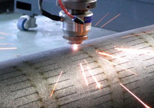
Lathe numerical control machining is a high-precision and high-efficiency automated machine tool processing method for completing various machining mechanical parts. In the process of lathe numerical control machining, it is necessary to prepare numerical control machine tool processing programs and carry out reasonable process planning to ensure the efficiency and accuracy of the machining process. The processing objects of lathe numerical control machining include rotating body parts and various flat face parts, etc. the programming route arrangement of 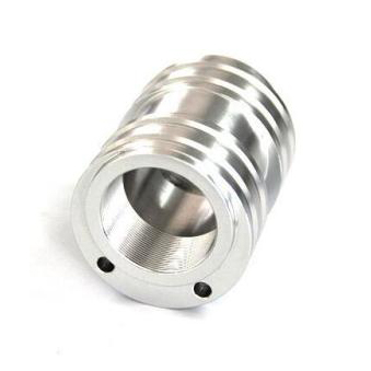 lathe numerical control machining should be considered from the following three aspects: 1. Process route (1) Analyze the part drawing requirements, blank conditions, and determine the process plan and processing route. For example, for short shaft parts, the axis line is the process reference, and the outer circle is clamped with a three-jaw self-centering chuck, and the rough finishing is completed in one clamping. (2) Economical numerical control lathes are selected according to the requirements of the part drawings, such as CJK6136D numerical control horizontal lathes. (3) According to the processing requirements, four tools are selected, T01 is the roughing tool, and 90 is the outer circle turning tool; T02 is the finishing tool, and the pointed turning tool is selected; T03 is the grooving tool, and the tool width is 4mm; T04 is the 60 thread tool. (4) The cutting amount is determined according to the performance of the machine tool, the relevant manual and the actual experience. 2. Step sequence The step sequence mainly has the following four steps: (1) Rough turning outer circle: The step cutting route is basically used, which is convenient for numerical calculation during programming. The arc part can be cut by concentric turning arc method, which is divided into three knives. (2) From right to left to fine turning right end face and each outer circle surface: chamfered cutting thread on the right end face of the turning outer circle turning φ 16mm outer circle turning R3mm arc turning φ 22mm outer circle. (3) Grooving. (4) Turning thread, cutting. 3. Tool route When arranging the finishing process that can be carried out with one or more knives, the final contour of its parts should be continuously processed by the last knife. At this point, the position of the machining tool in and out should be considered properly, and try not to arrange cutting and cutting or tool change and pause in a continuous profile, so as to avoid elastic deformation due to sudden changes in cutting force, resulting in surface scratches, shape mutations, or residual knife marks on the smooth connection profile.
Hello! Welcome to EMAR company website!
 English
 » »
» »
 Spanish
 Arabic
 Spanish Basque
 Portuguese
 Belarusian
 Japanese
 Russian
 Icelandic
 Bulgarian
 Azerbaijani
 Estonian
 Irish
Irish Polish
 Persian
 Boolean
 Danish
 German
 French
 Filipino
 Finnish
 Korean
 Dutch
Dutch Galician
 Catalan
 Czech
Czech Croatian
 Latin
Latin Latvian
 Romanian
 Maltese
 Malay
Malay Macedonian
 Norwegian
 Swedish
 Serbian
 Slovak
 Slovenian
 Swahili
 Thai
Thai Turkish
 Welsh
Welsh Urdu
Urdu Ukrainian
 Greek
Greek Hungarian
 Italian
 Yiddish
 Indonesian
 Vietnamese
 简体中文
简体中文 Haitian Creole


