Spanish
 Arabic
 French
 Portuguese
 Belarusian
 Japanese
 Russian
 Malay
Malay Icelandic
 Bulgarian
 Azerbaijani
 Estonian
 Irish
Irish Polish
 Persian
 Boolean
 Danish
 German
 Filipino
 Finnish
 Korean
 Dutch
Dutch Galician
 Catalan
 Czech
Czech Croatian
 Latin
Latin Latvian
 Romanian
 Maltese
 Macedonian
 Norwegian
 Swedish
 Serbian
 Slovak
 Slovenian
 Swahili
 Thai
Thai Turkish
 Welsh
Welsh Urdu
Urdu Ukrainian
 Greek
Greek Hungarian
 Italian
 Yiddish
 Indonesian
 Vietnamese
 Haitian Creole
 Spanish Basque

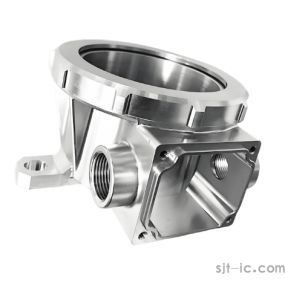
Introduction to the machining characteristics of precision automatic lathes
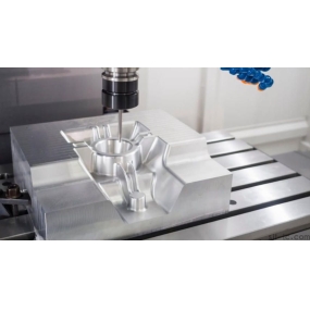
 Precision automatic lathe is an efficient automated machine tool. Precision automatic lathe processing is different from ordinary machine tool processing. When machining parts on a precision automatic lathe, various operations required in the processing process (such as starting and stopping of the spindle, commutation and speed change, feeding of the workpiece or tool, tool selection, coolant supply, etc.) and the shape and size of the parts are written into numerical control processing programs according to the specified coding method, and input into the numerical control device. Then the numerical control device processes and calculates the input information, and controls the servo drive system to coordinate the movement of the coordinate axis, so as to realize the relative movement between the tool and the workpiece and complete the processing of the parts. When the workpiece to be machined is changed, in addition to re-clamping the workpiece and changing the tool, only the replacement program is required.
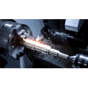
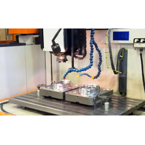
Precision automatic lathes use numerical control devices or electronic computers to completely or partially replace various actions of general-purpose machine tools when machining parts, such as starting, machining sequence, changing cutting dosage, spindle speed change, selecting tools, coolant start and stop, and parking. Therefore, precision automatic lathes are machine tools equipped with numerical control systems, which use digital signals to control the movement of the machine tool and its processing process. The basic principle of numerical control is linear interpolation, which is to calculate the coordinate values of several intermediate points between the starting and ending points of the tool movement according to the requirements of the feed speed.
At present, in the multi-coordinate linkage numerical control system, the most extensive linear interpolation algorithm is the data sampling interpolation algorithm, which is characterized by the interpolation operation is completed in two steps. The first step is coarse interpolation, which is to insert several knife check points between the connections of a given starting knife check point, that is, for each motion coordinate, several small displacements are used to approximate, and the length of each small displacement is equal to Delta L and is related to the given feed rate. Coarse interpolation is calculated only once in each interpolation operation cycle, and the length of each small displacement is related to Delta L and the given feed rate F and interpolation period T, that is, Delta L = FT. The second step is fine interpolation, which is to do "densification of data points" on each tiny displacement calculated by rough interpolation. Coarse interpolation calculates the coordinate position increment value in each interpolation cycle, while fine interpolation calculates the sampling position increment value and the interpolation output instruction position increment value in each sampling cycle, and then calculates the corresponding interpolation instruction position and the actual feedback position of each coordinate axis, and compares the two to obtain the follow error. According to the obtained follow error, the feed speed instruction of the corresponding axis is calculated and output to the drive device. Usually the interpolation period can be an integer multiple of the sampling period.